
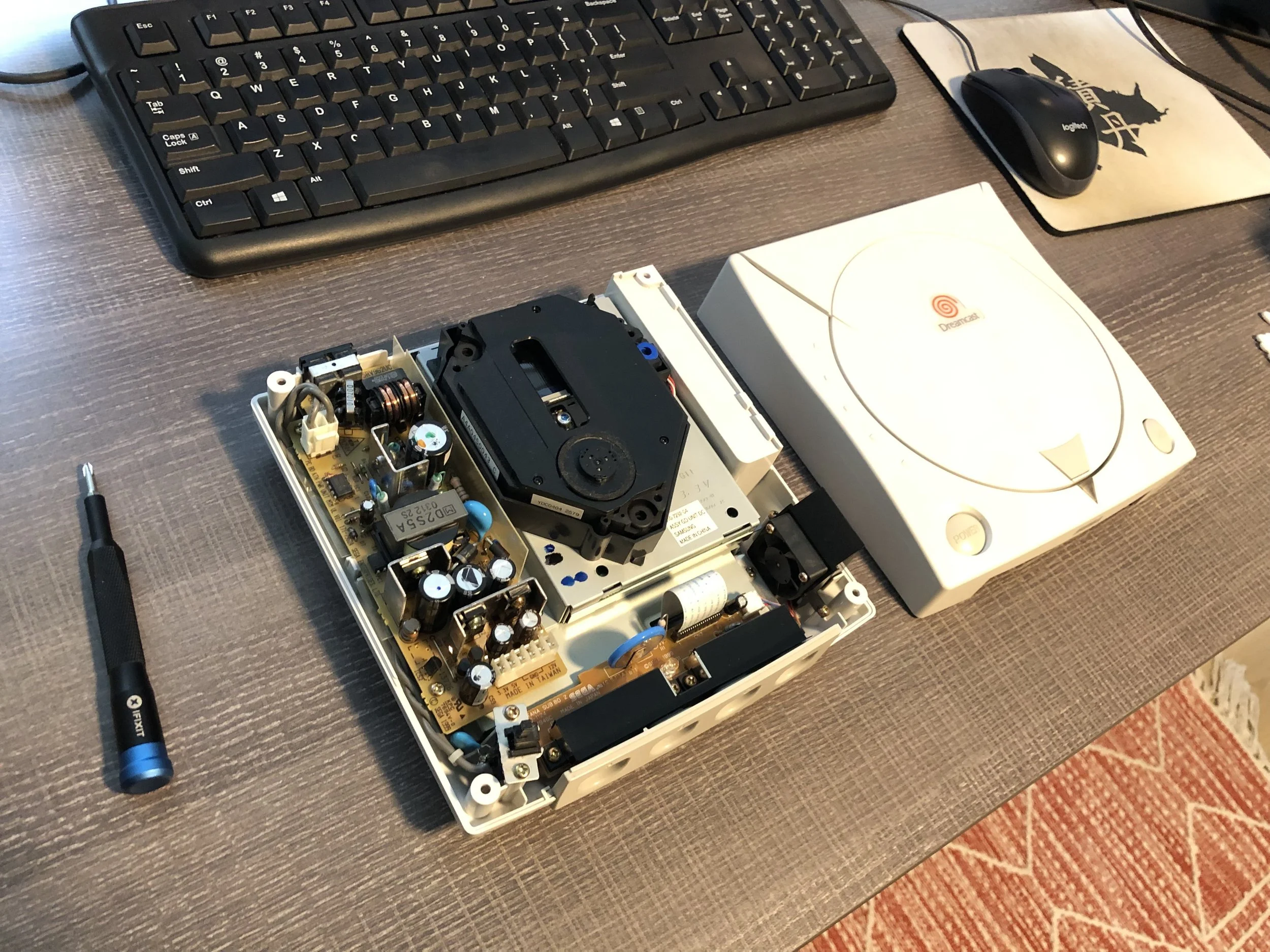
Dreamcast Repairs and Mods
If you own a Sega Dreamcast in 2026 (or beyond) then your machine could almost certainly use a little work. Amazing as Sega’s final game console was at the turn of the millennium—and still is, by the way!—there are at least one or two adjustments you probably should make to breathe new life into your Dreamcast.
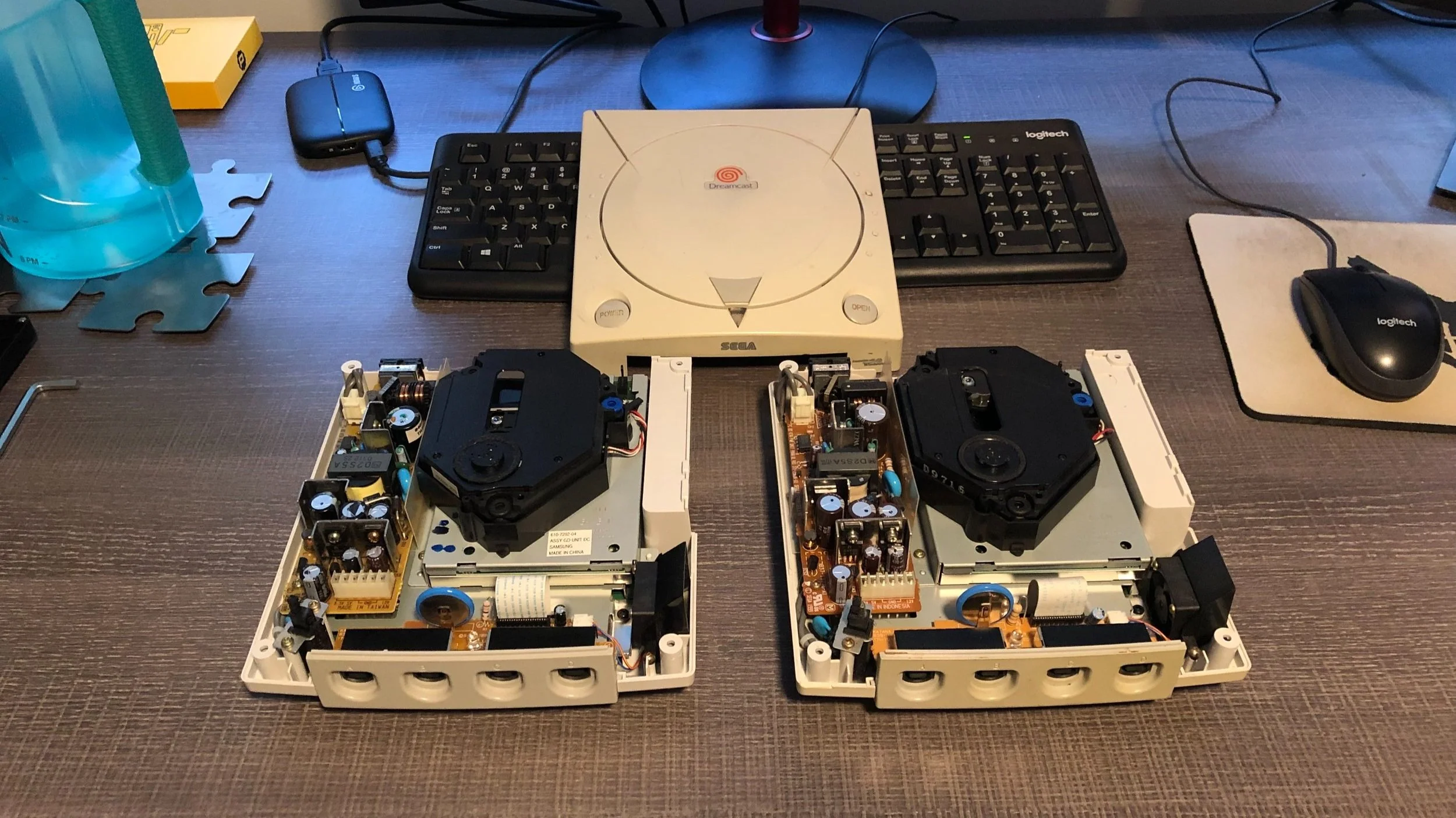
Today we will cover four such improvements, and give you our impressions of the modding process for each.
Clock Battery Modification
Cooling Fan Upgrade
Power Supply Unit Replacement
GDEMU Installation
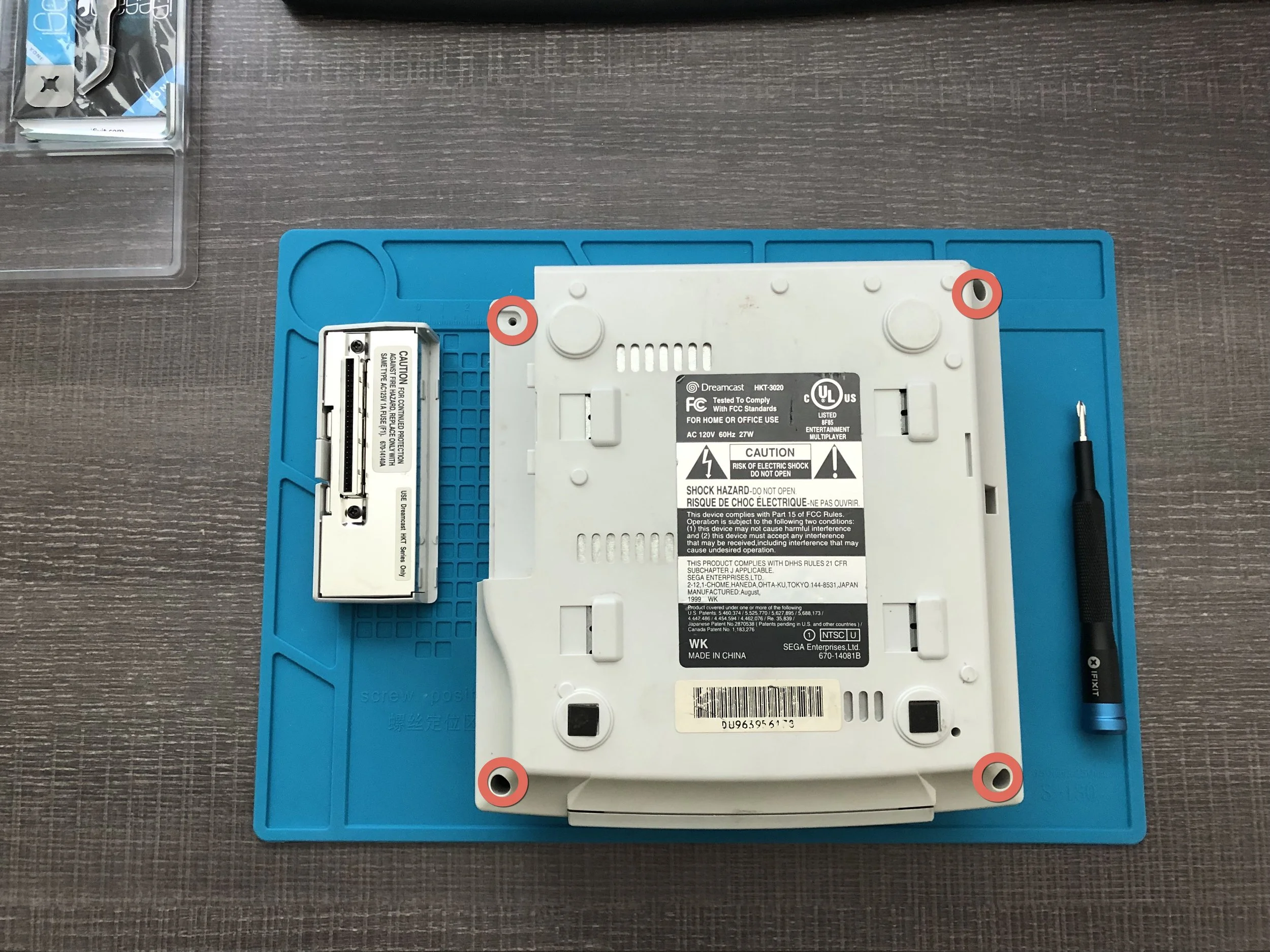
To get started, we’ll need to open up the Dreamcast shell. This is as simple as removing four screws from the bottom of the console, one on each corner. Just note, the network adapter needs to be taken off before you can reach one of those screws.
Clock Battery Modification
Requires Soldering, but…
A beginner-friendly soldering project
Products Used:
As mentioned in the points above, this mod requires some soldering. However it’s actually a very beginner-friendly soldering project. (And probably even easier if you happen to have a desoldering gun, which I did not.) Here’s how to tackle it.
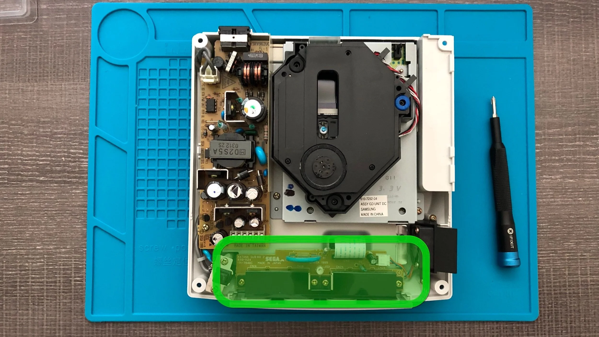
The component with the clock battery is near the front the Dreamcast. It’s actually the board for where the controllers plug into machine.
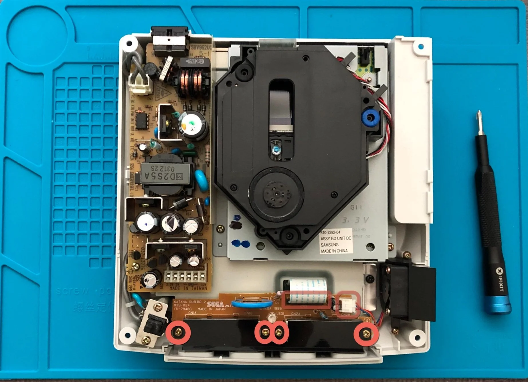
You’ll want to remove this board by unscrewing four screws and detaching one ribbon cable, and the socket powering the fan. One these six things are unfastened, you can simply lift the board out the Dreamcast.
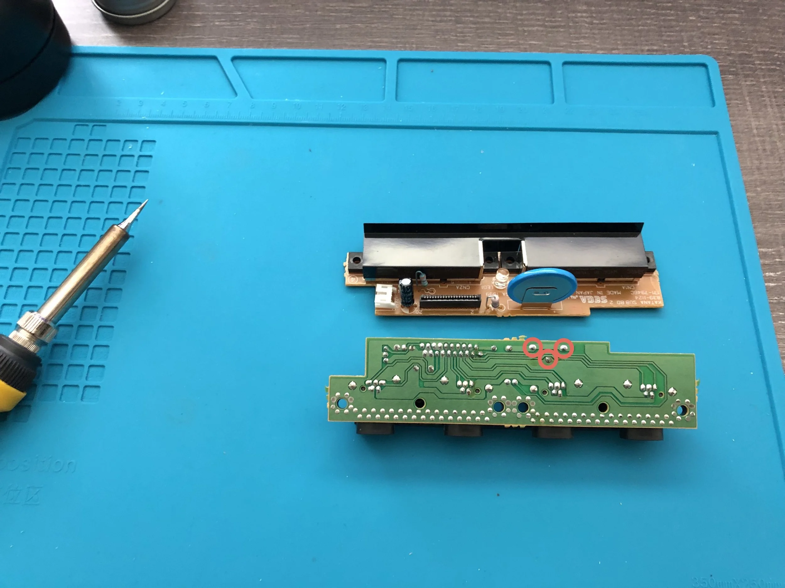
In order to replace the clock battery, you will need to desolder three points on the bottom of the board. They are highlighted above. Essentially the battery stand has three metal pegs that slip through the board and get soldered in place on the underside. We’ll just need to remove those solder joints for now and redo them later when our replacement battery is in seated there instead.
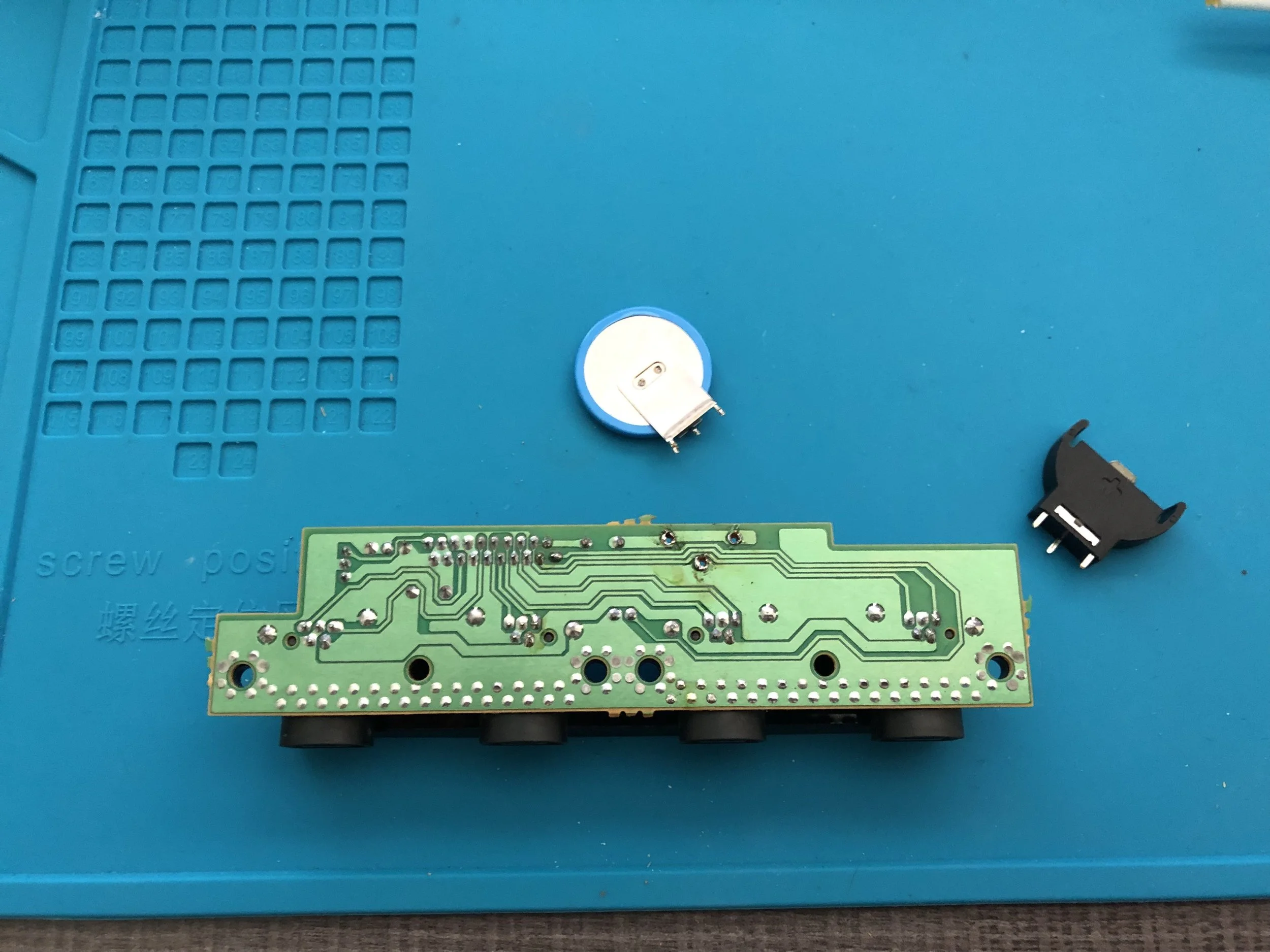
Using your soldering iron and a copper wick (also called a desoldering braid), remove the solder from these joints to free the old battery. Eventually the battery stand will simply fall out. For our replacement battery, we will actually install a cradle for coin battery. This way we won’t have to get out our soldering equipment every time we want to replace this dumb thing.
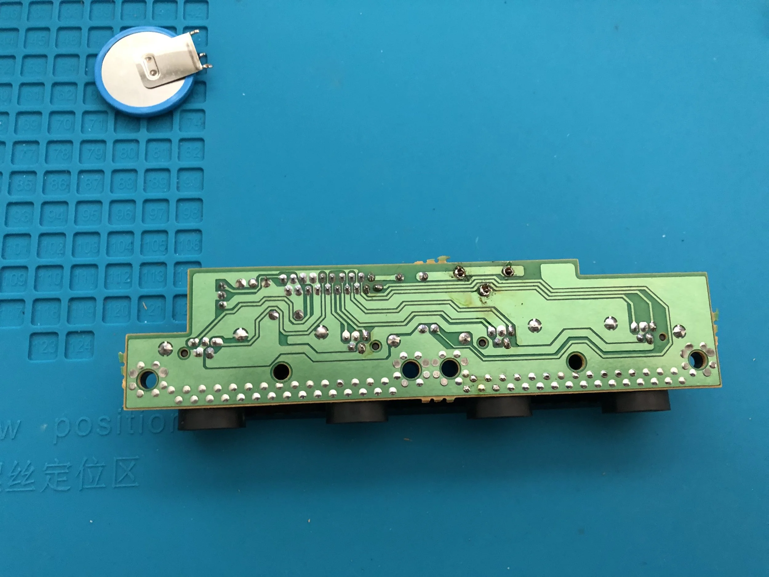
Seat the replacement battery stand in the same three holes. Now you can solder this joints on the bottom of the board.
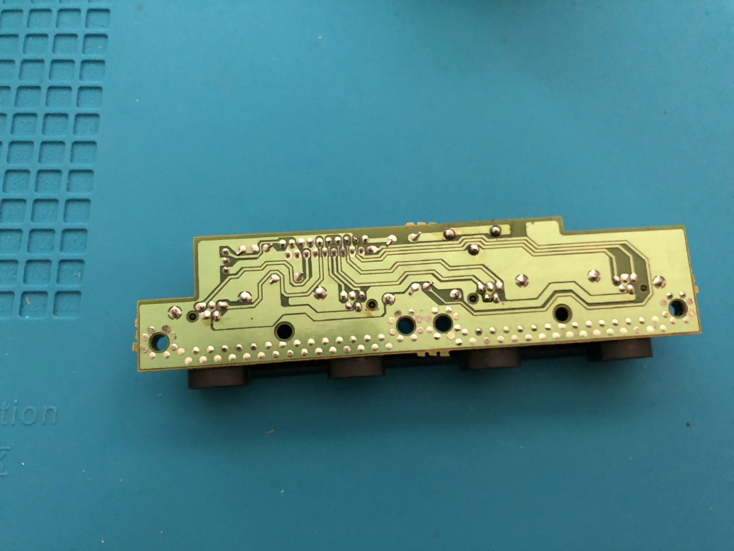
The newly soldered joints should look something like the image above.
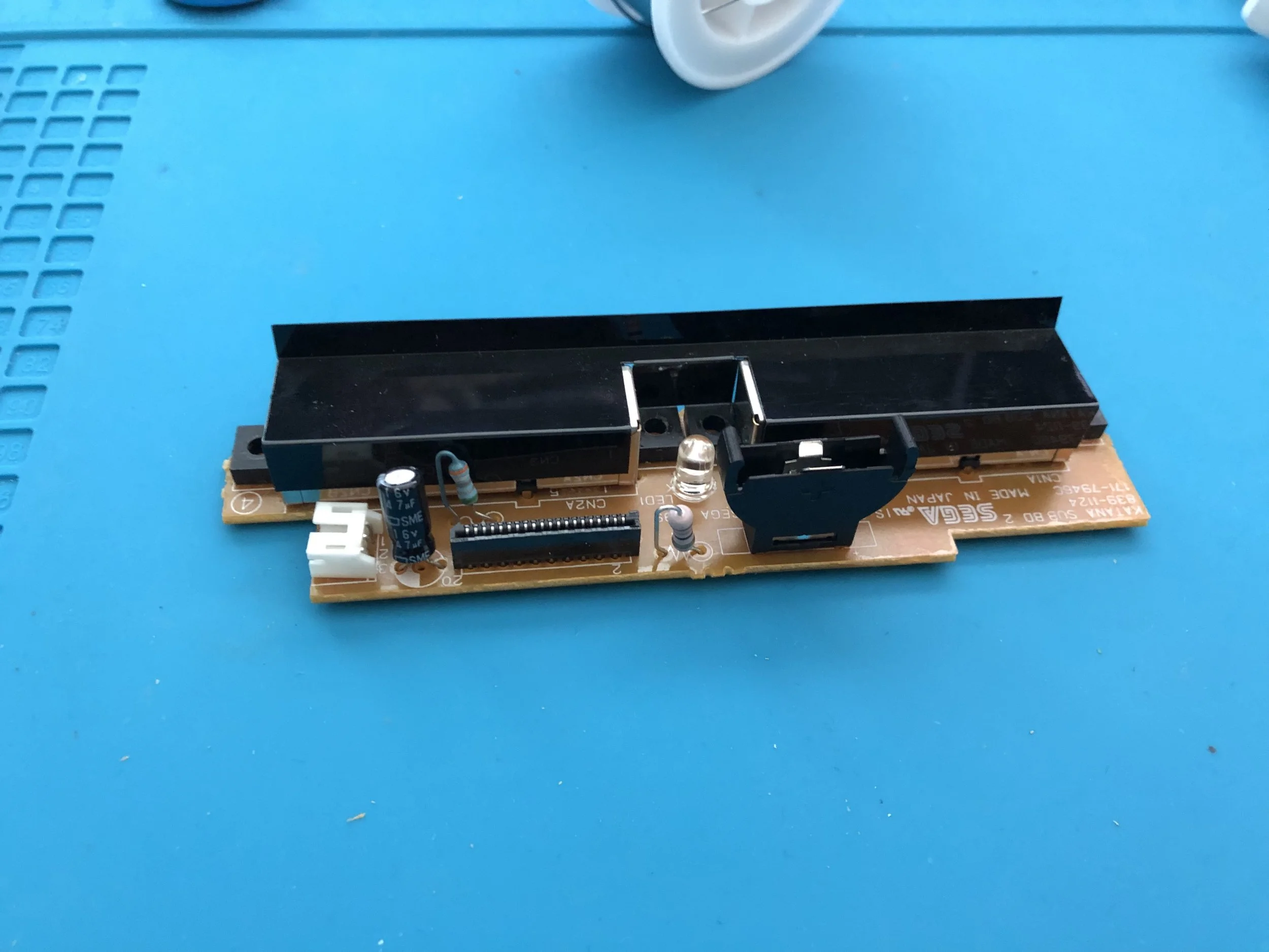
And that’s pretty much it for this mod. Just install an appropriate battery in the newly stalled cradle and put the board back in your console the same way you found it.
You will still need to entered the date/time once more the next time your boot up your Dreamcast. But then you won’t have to worry about again. At least not for a good long while!
Cooling Fan Upgrade
No soldering required or shell alterations needed, however…
It can actually be quite tricky to set up the disk tray door hinge.
Products Used:
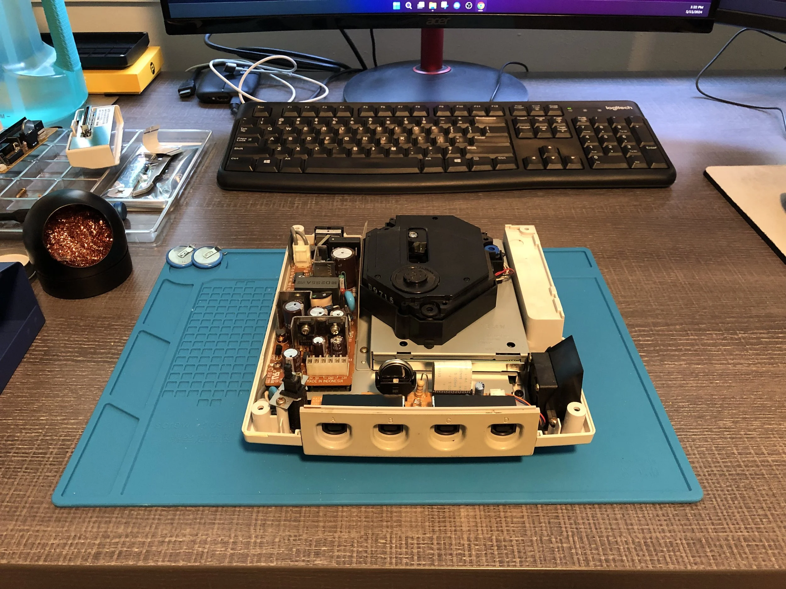
This cooling fan upgrade should be pretty easy, except the new fan is bigger than the original. Depending on the 3D-printed parts you use, accommodating the bigger fan could be a pretty big pain. In my case, the 3D-printed parts I had didn’t fit the Dreamcast very precisely and the new latch parts were completely useless extremely difficult to use. It took some MacGuyver’ing of a spring to get that disk drive tray to simply remain closed, but we did it!
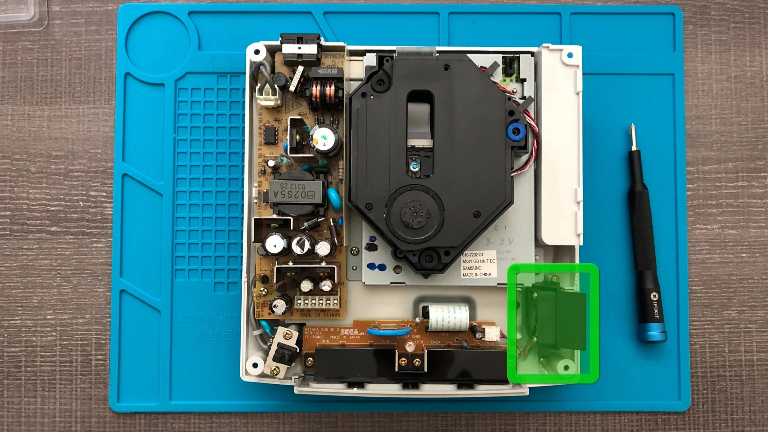
The fan is found at the front right corner of the Dreamcast. It’s just to the right of the last component we worked on.
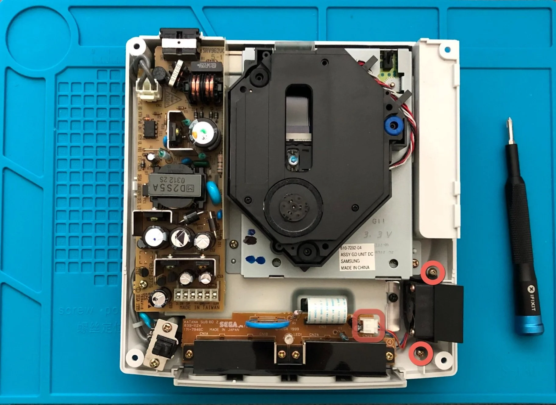
There are two screws to remove to release the fan, and don’t forget to disconnect the cable connecting it to the front circuitboard.
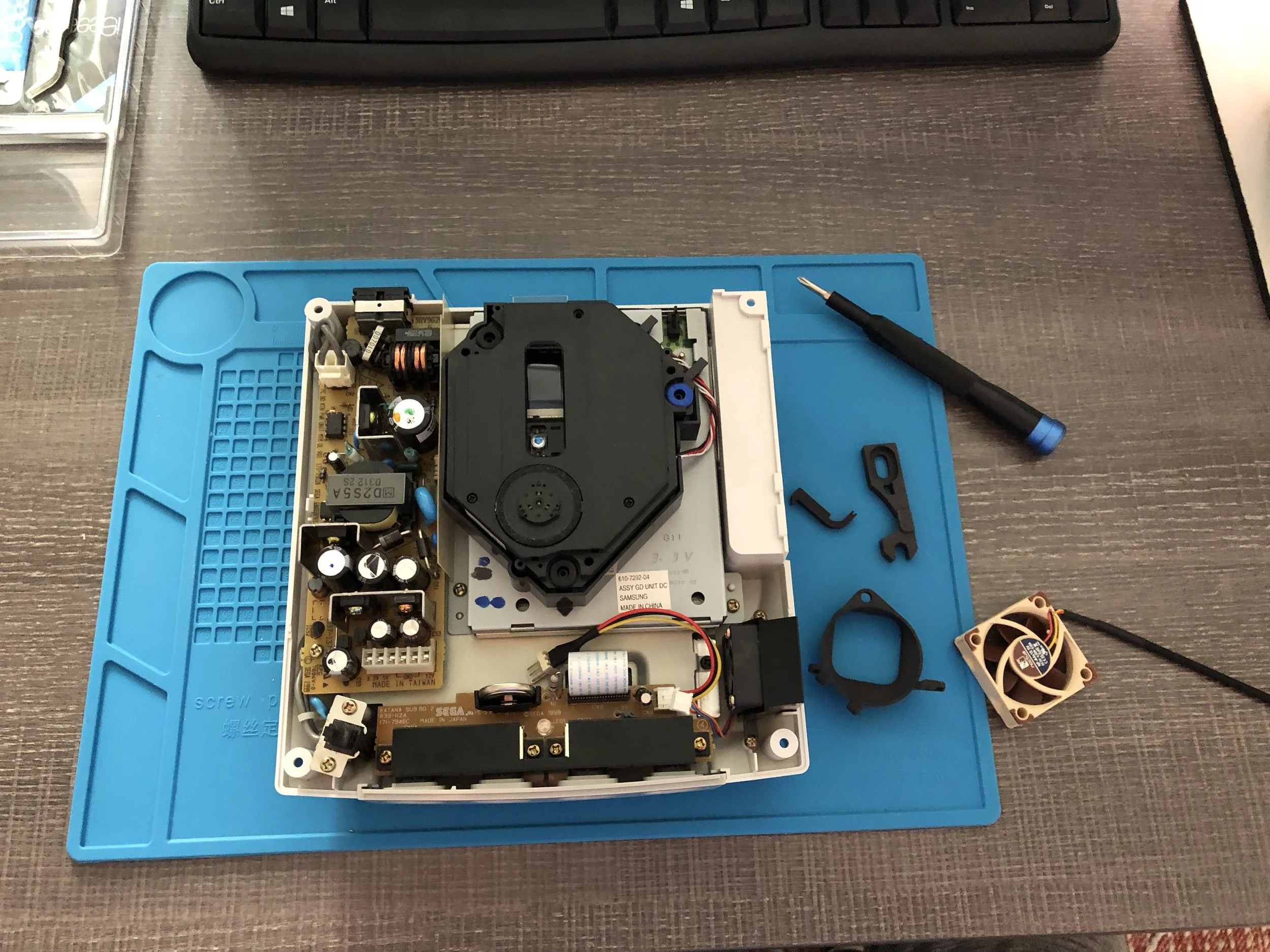
Once the old fan has been removed, you can install the housing for the new fan, using the same two screw holes from before. It should look something like the image below.
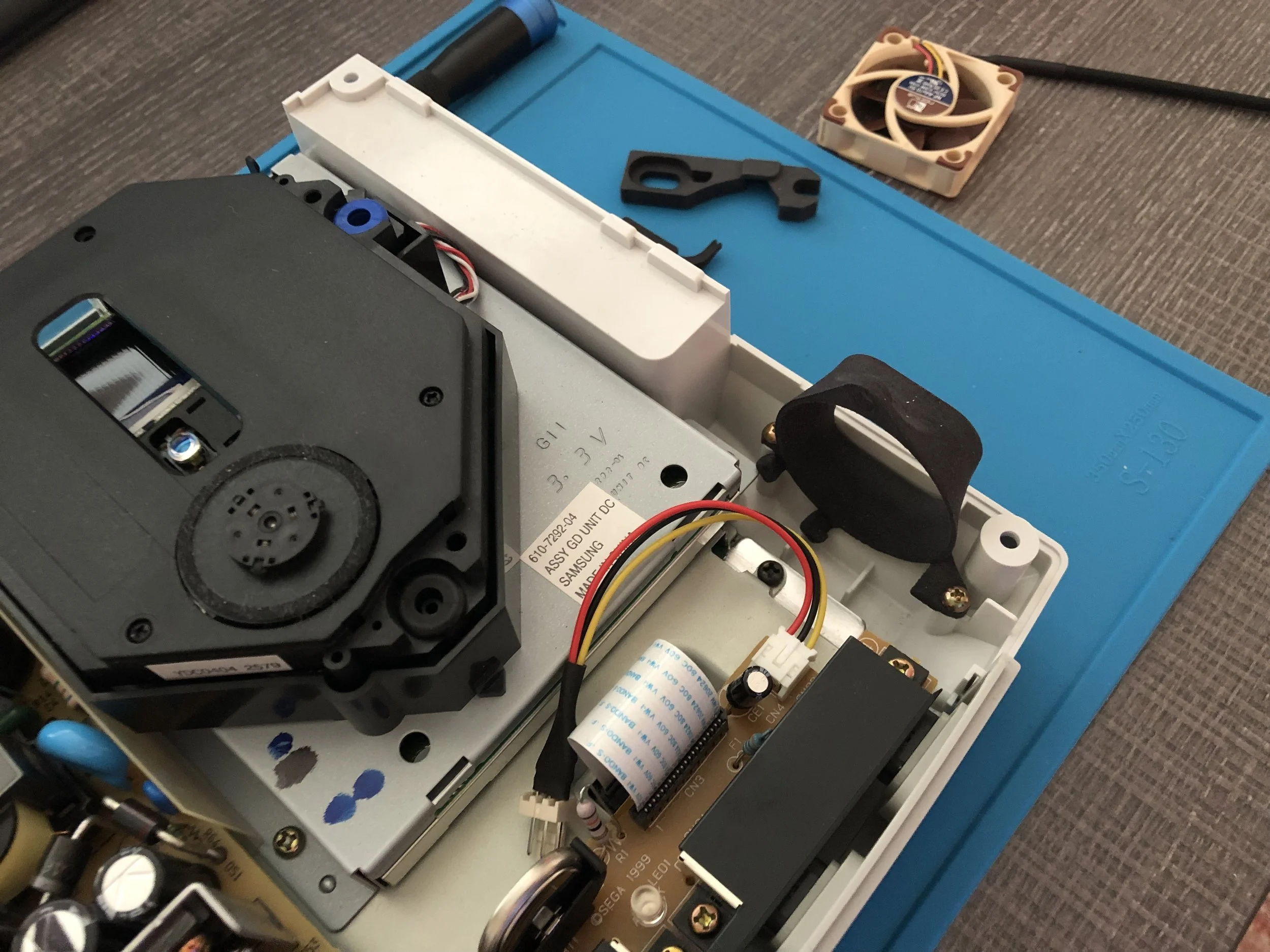
Next, secure the new fan to the housing was screw at the top. It should have just a enough room to sit snugly in there.
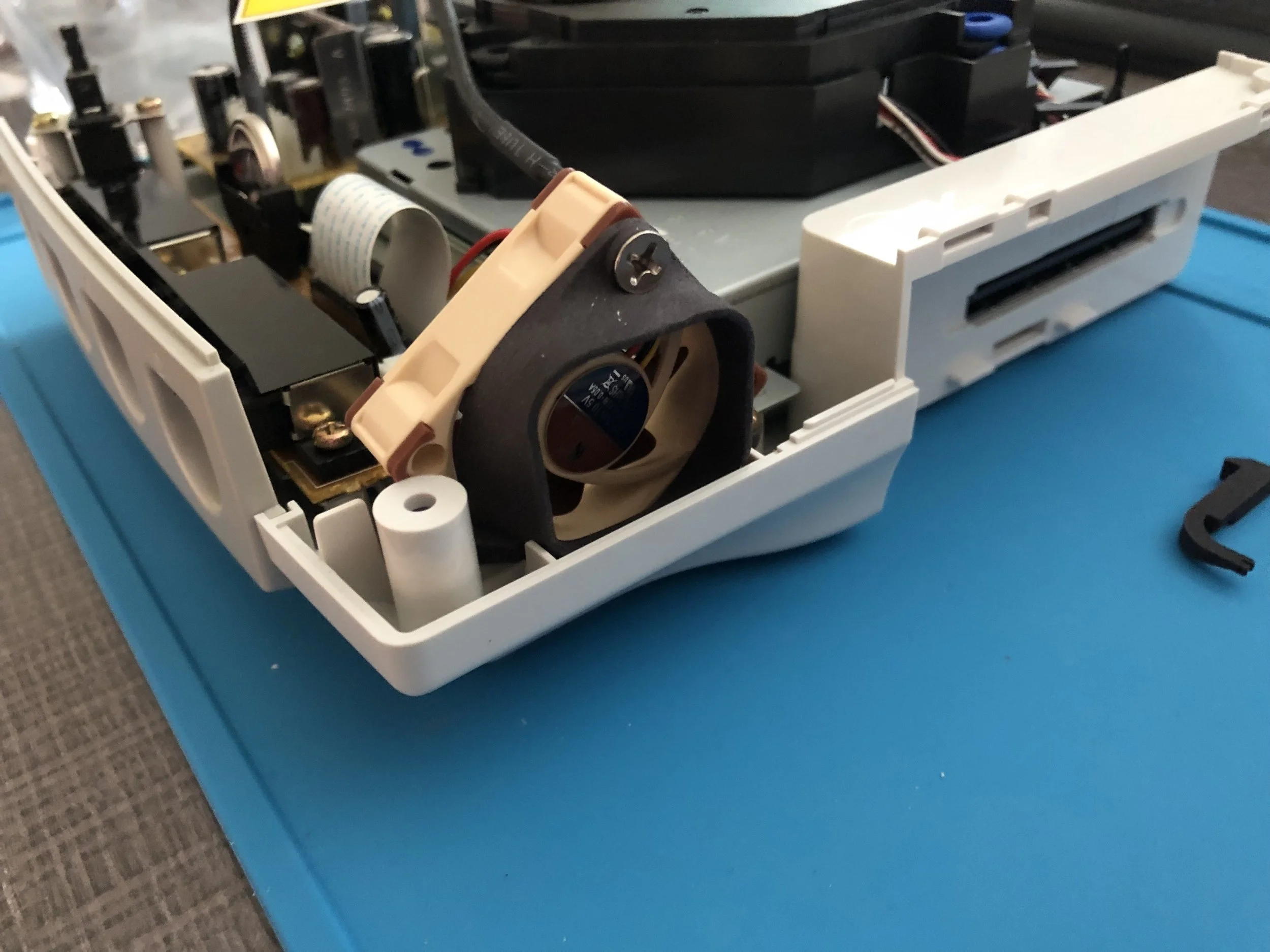
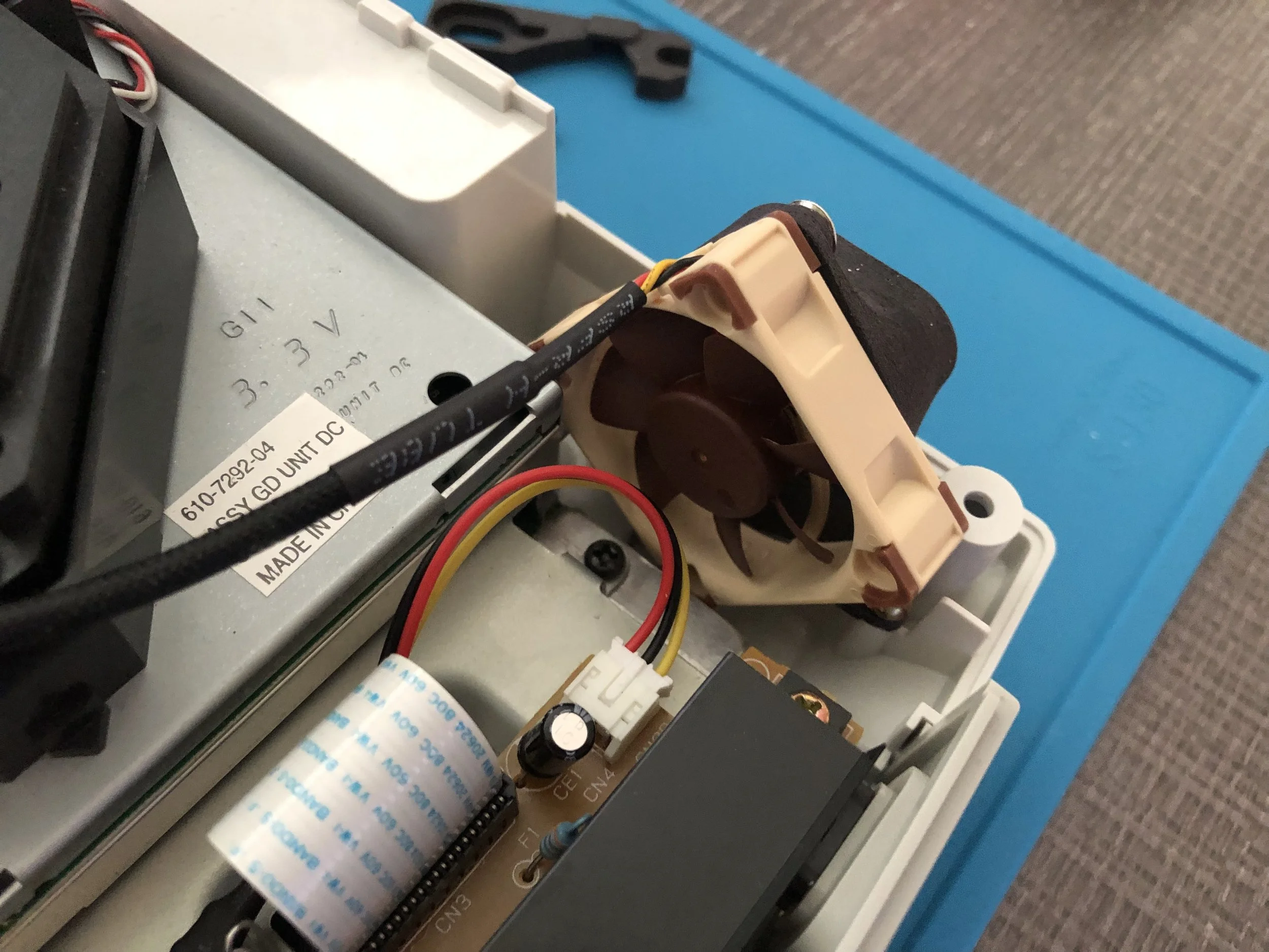
Ok, this next part with the disc tray hinge is a real headache, and I apologize in advance. Start by removing the two screws from underneath the tray latching mechanism to release it. Keep those screws handy, as well as the original spring, because we will use them in just a second.
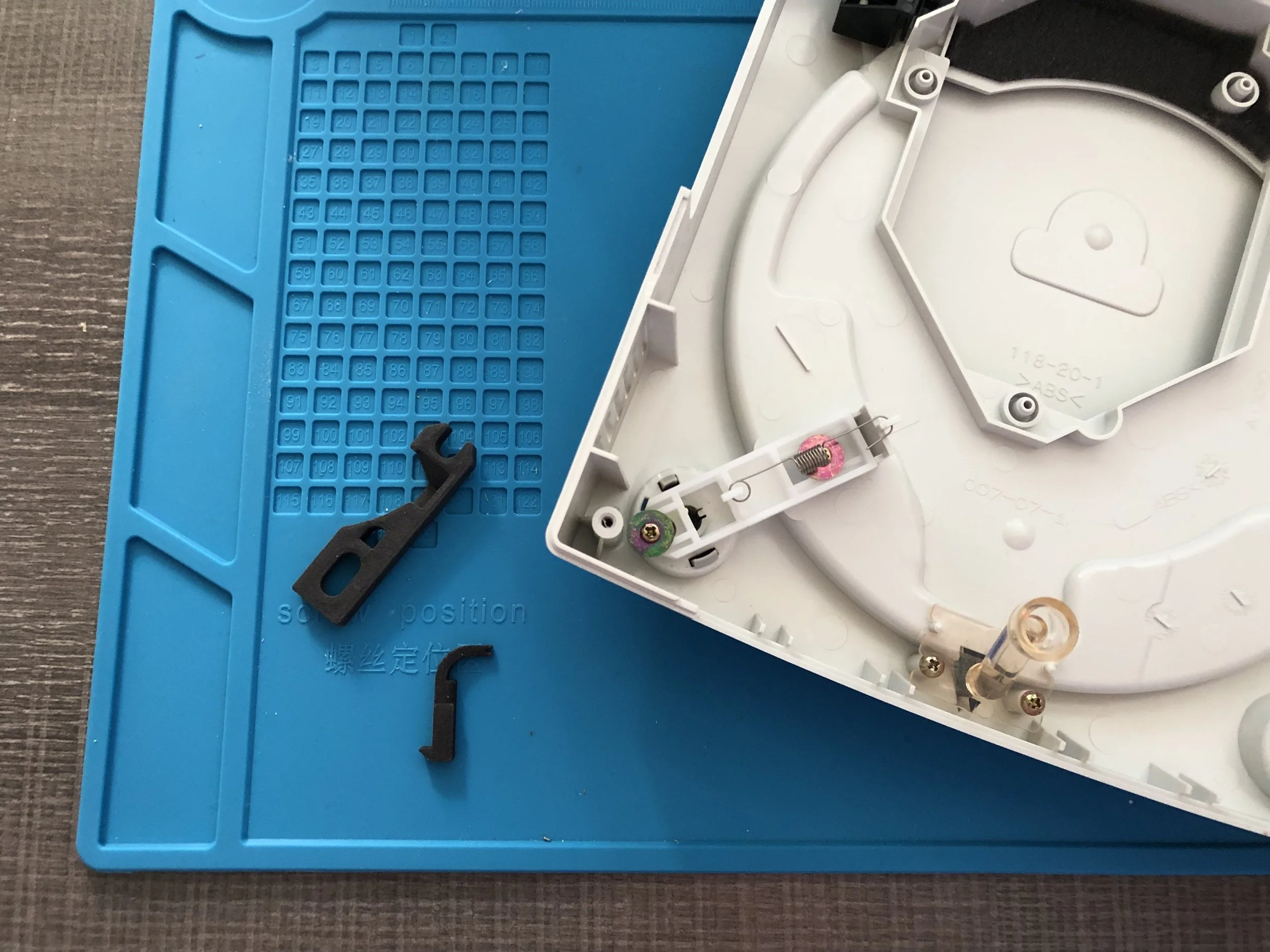
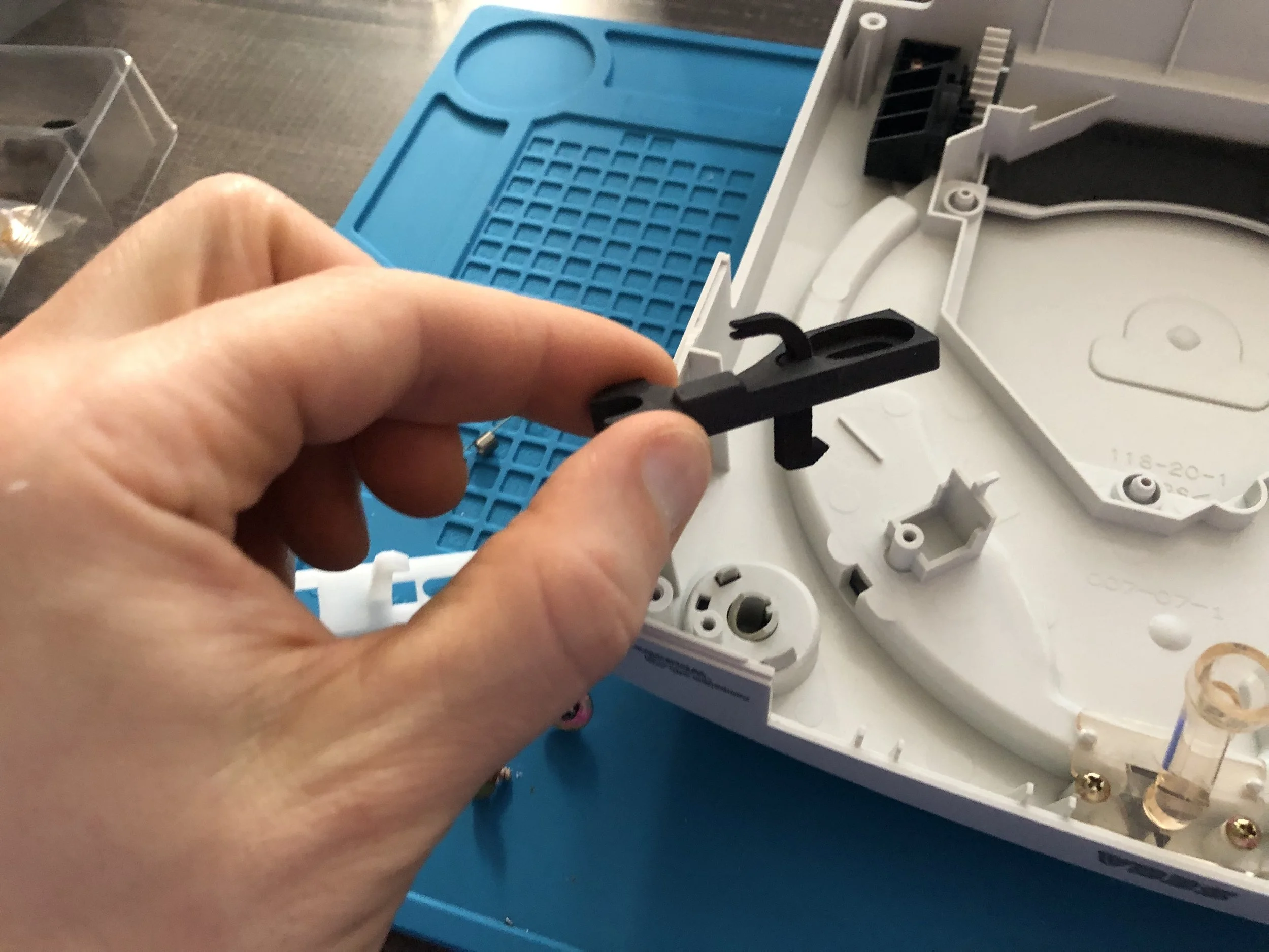
Orient the replacement tray hatch pieces as shown in the photo below. The actual latching bit need to extend into the bottom of the tray, while the thinner bit on the other side pokes the opposite direction. While I had assumed that thinner bit connected to the spring, that’s not actually how I actually got mine to work.
With the replacement tray hatch pieces seated, it looked like this. Then I just used the saw two screws to secure them in place.
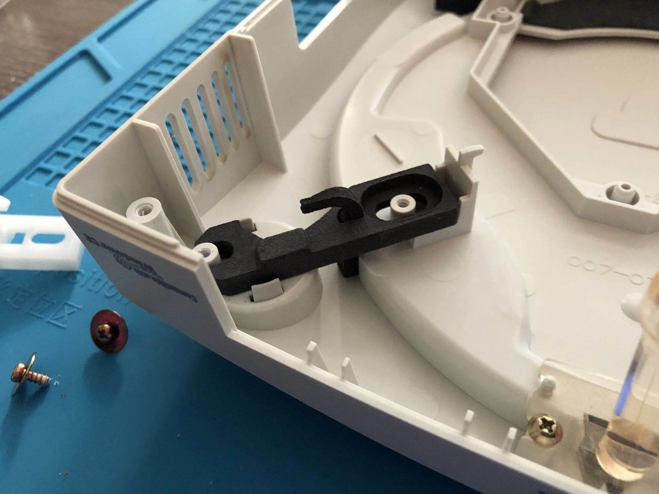
The way I finagled the spring to work here seems completely wrong to me…and yet it’s the only way I was able to get the new disc tray parts to latch. See the two images below for evidence of the carnage.
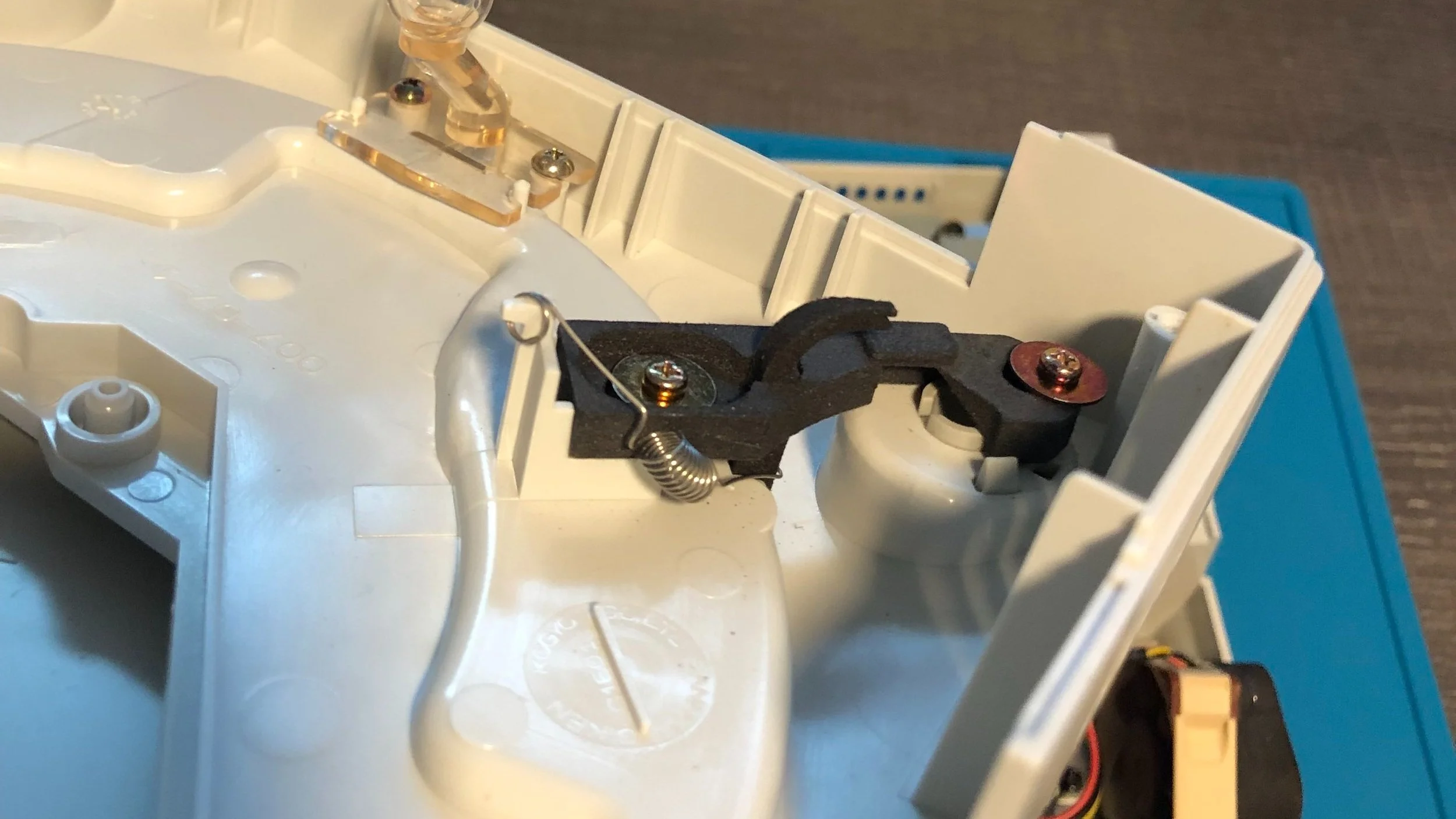
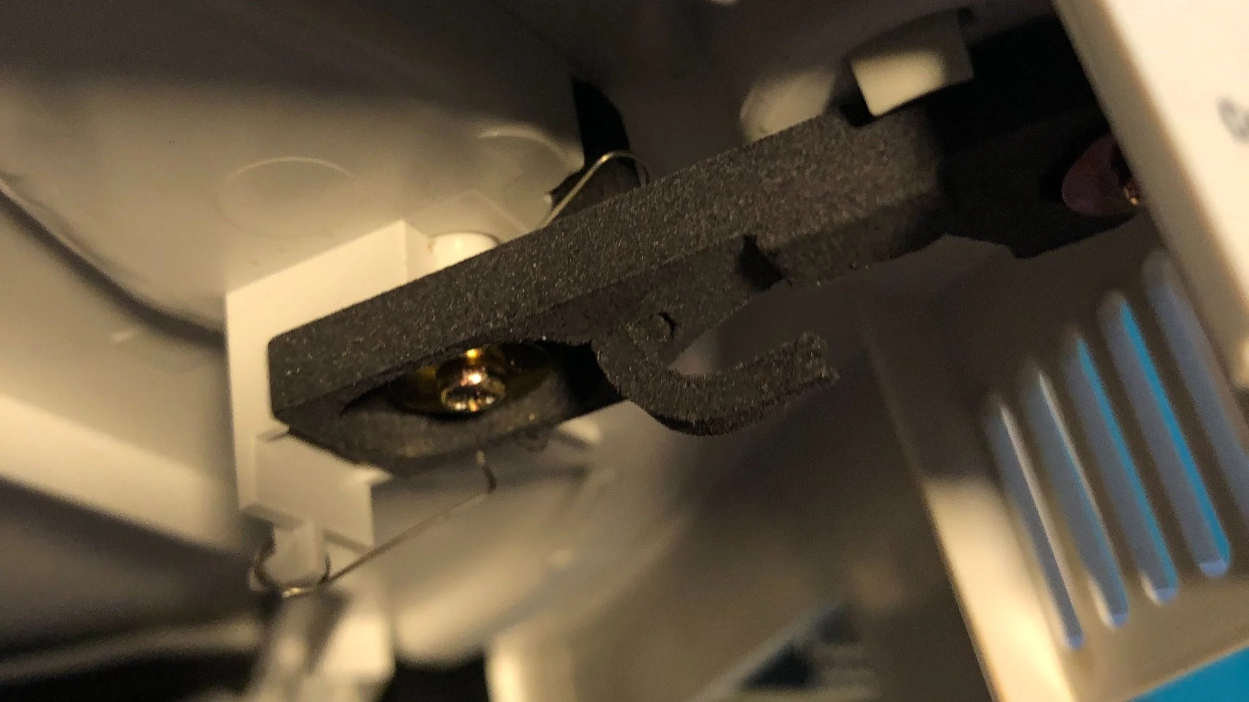
And that was that! After plugging the new fan in the old fan’s power cable, it worked great. I’m still pretty leery of this ramshackle disc tray latch situation, but it has actually been working so far. Great I’ll just be happy with it.
Power Supply Unit Replacement
Very easy upgrade, simple replacement
Pin connectors can be a bit finicky
Power port on the back of the Dreamcast might be an extremely tight fit
Products Used:
This replacement is very easy upgrade, just swap out the old bulky power supply unit and replace with a little circuit board. The pin connectors can be surprisingly finicky, however it’s still a really easy project. In my opinion, the one sticking point is that the replacement port on the back of the Dreamcast is a really tight fit, meaning you might have to physically force it into place.
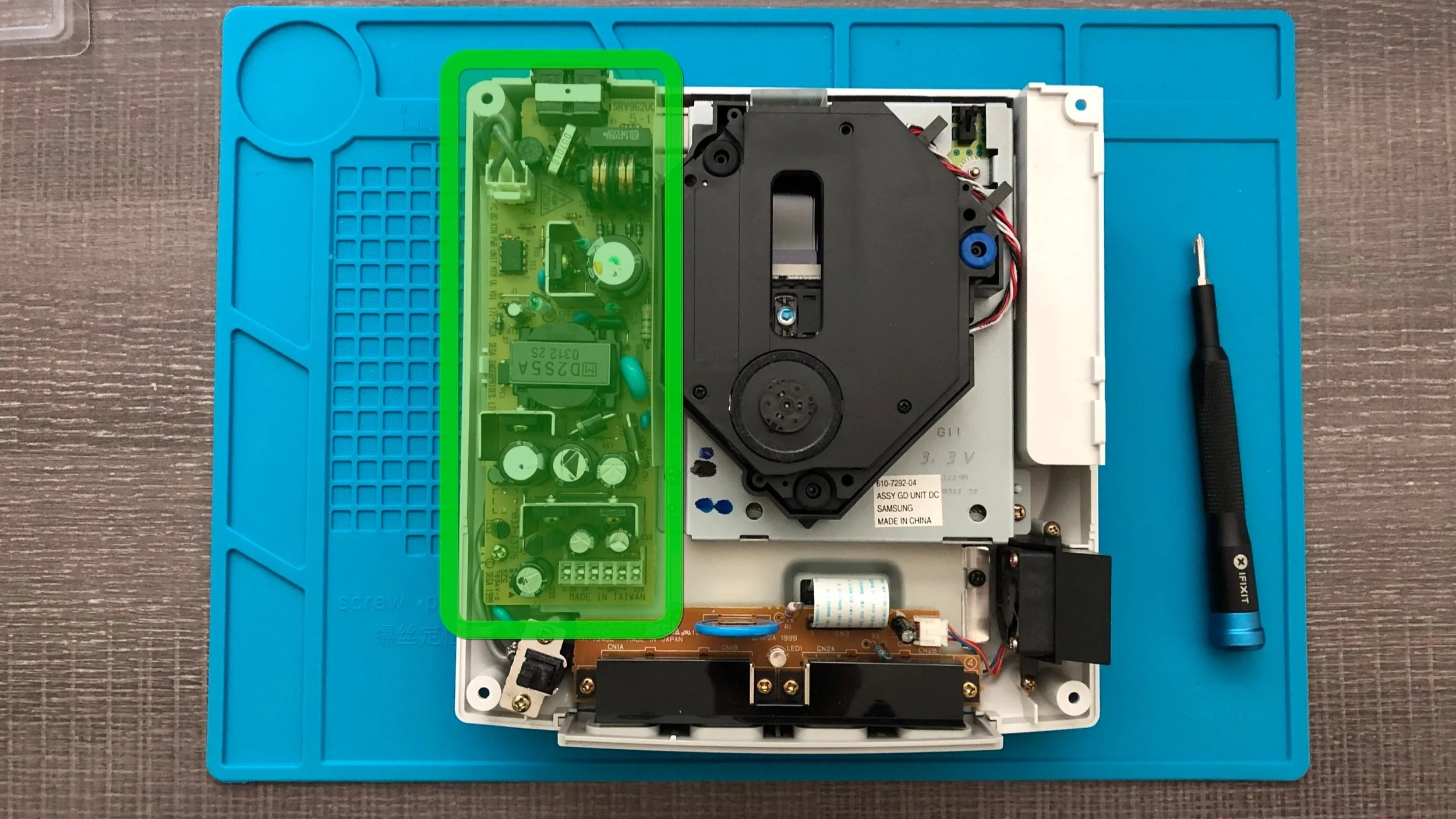
It’s honestly pretty hard to miss the power supply, as it takes up like a quarter of the space inside the Dreamcast and spans almost the entire left side. Just look at all those capacitors and stuff, that’s all coming out!
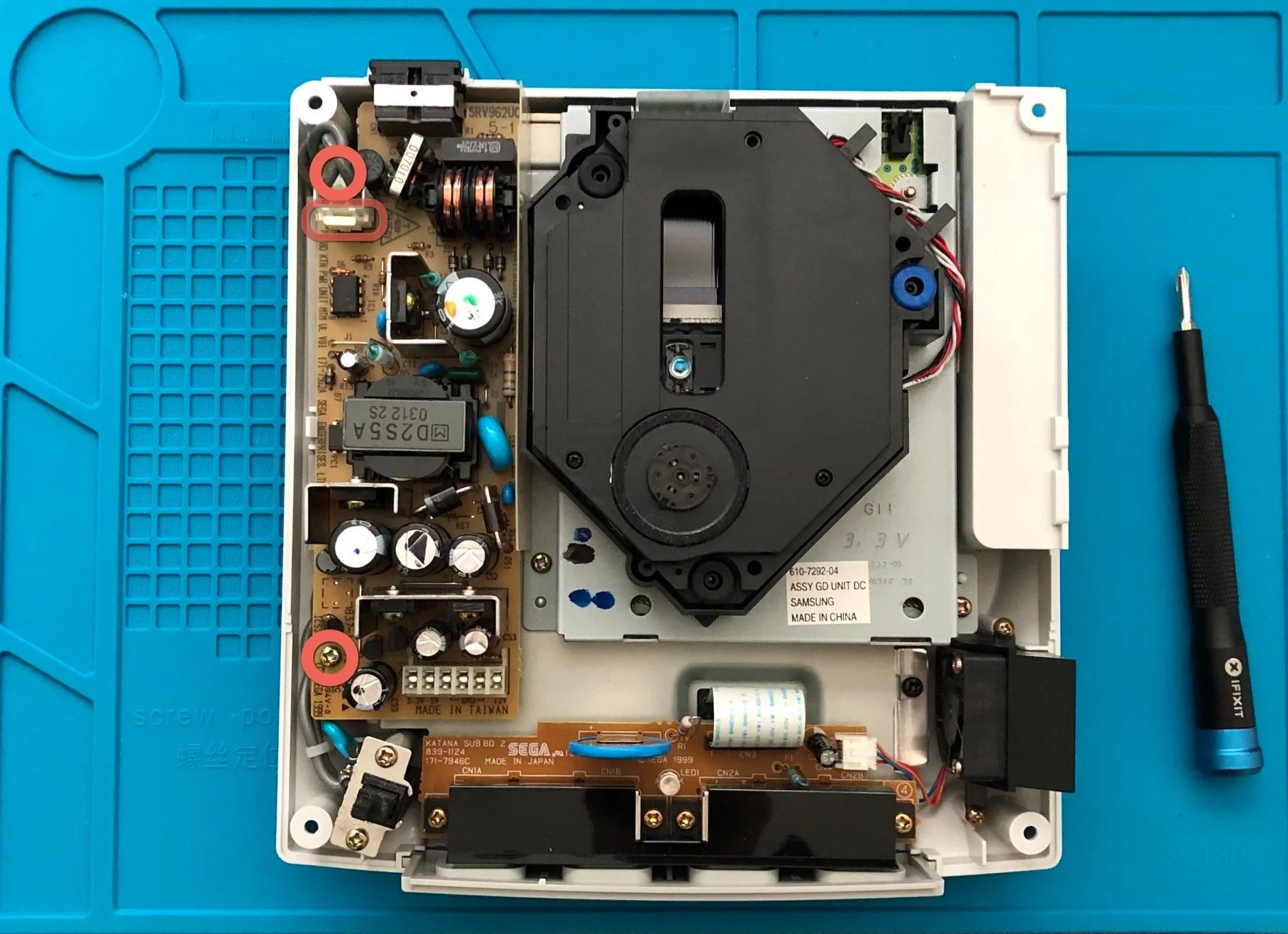
There are two screws that need to be removed to take out the power supply. Don’t forget to detach the cable near the upper left as well. Once that’s been disconnected, you can simply lift the power supply out. You might find that the pin connectors at the bottom right hand on a little tight, but getting the unit out should be pretty easy.
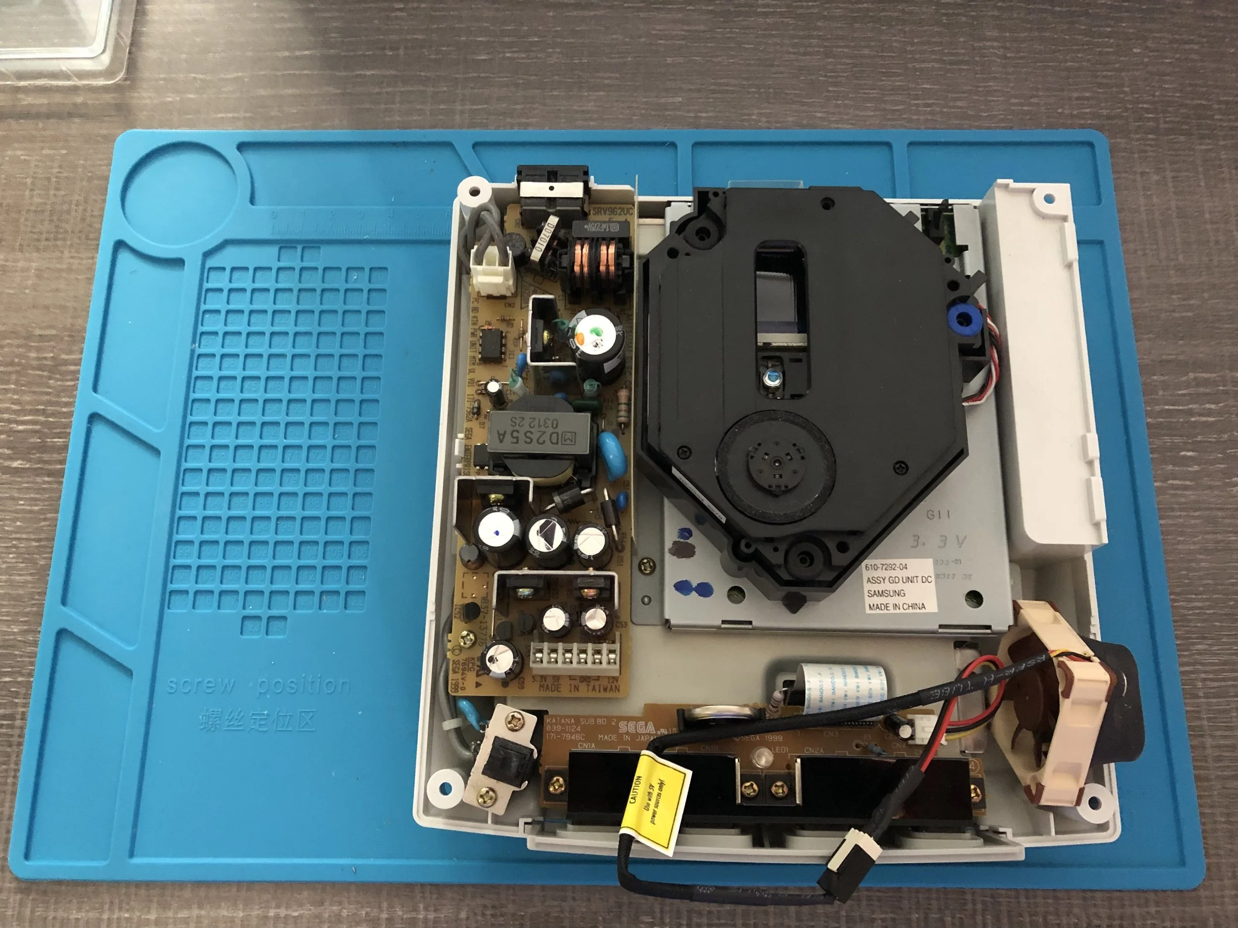
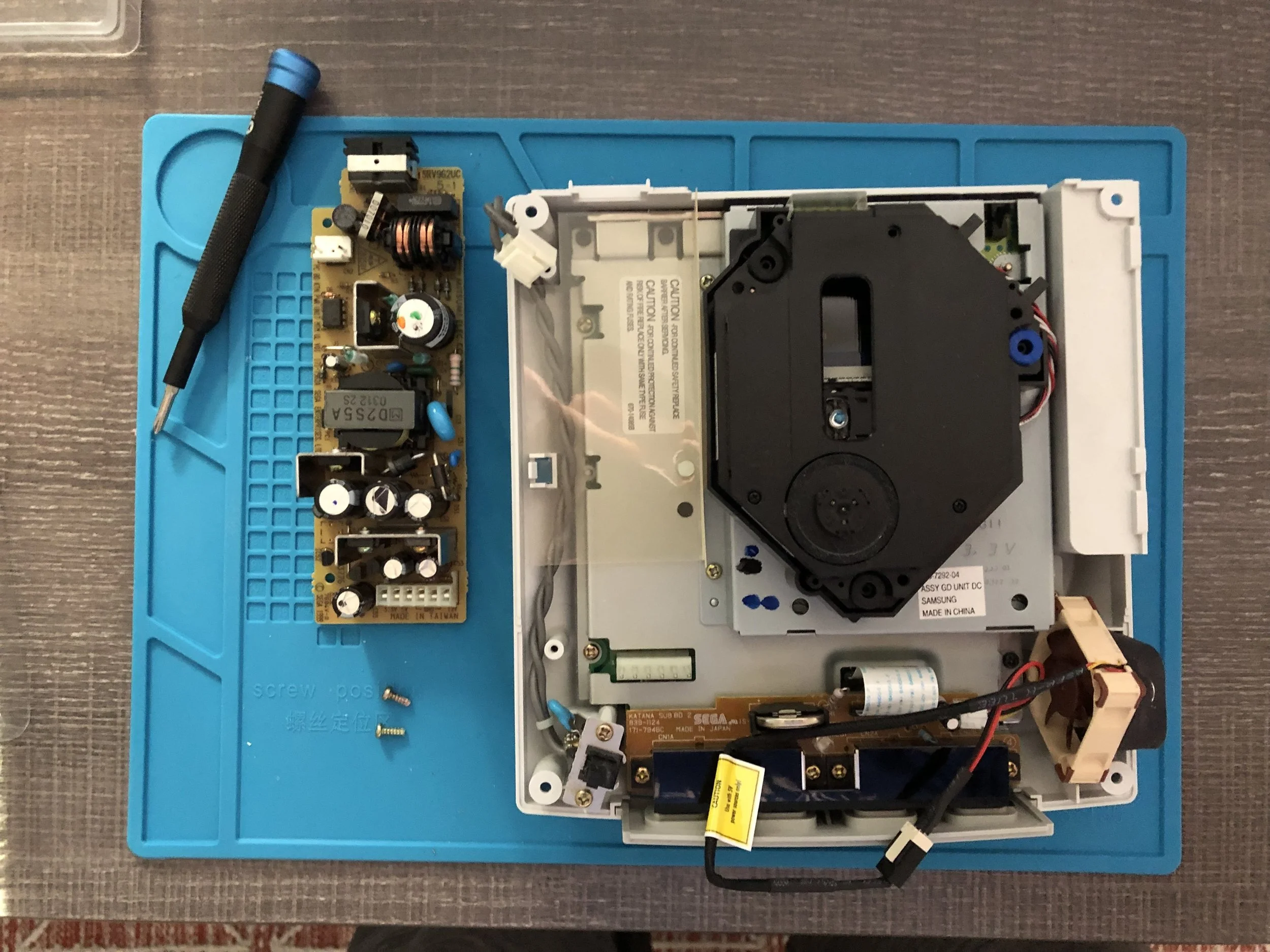
Comparing the size of the old power supply with the new, it’s kind of crazy how small the new one is. But a big reason for the size difference is that the new power cable the Dreamcast will be using has a big old brick to it. So a lot of these elements will now be external to the console’s body.
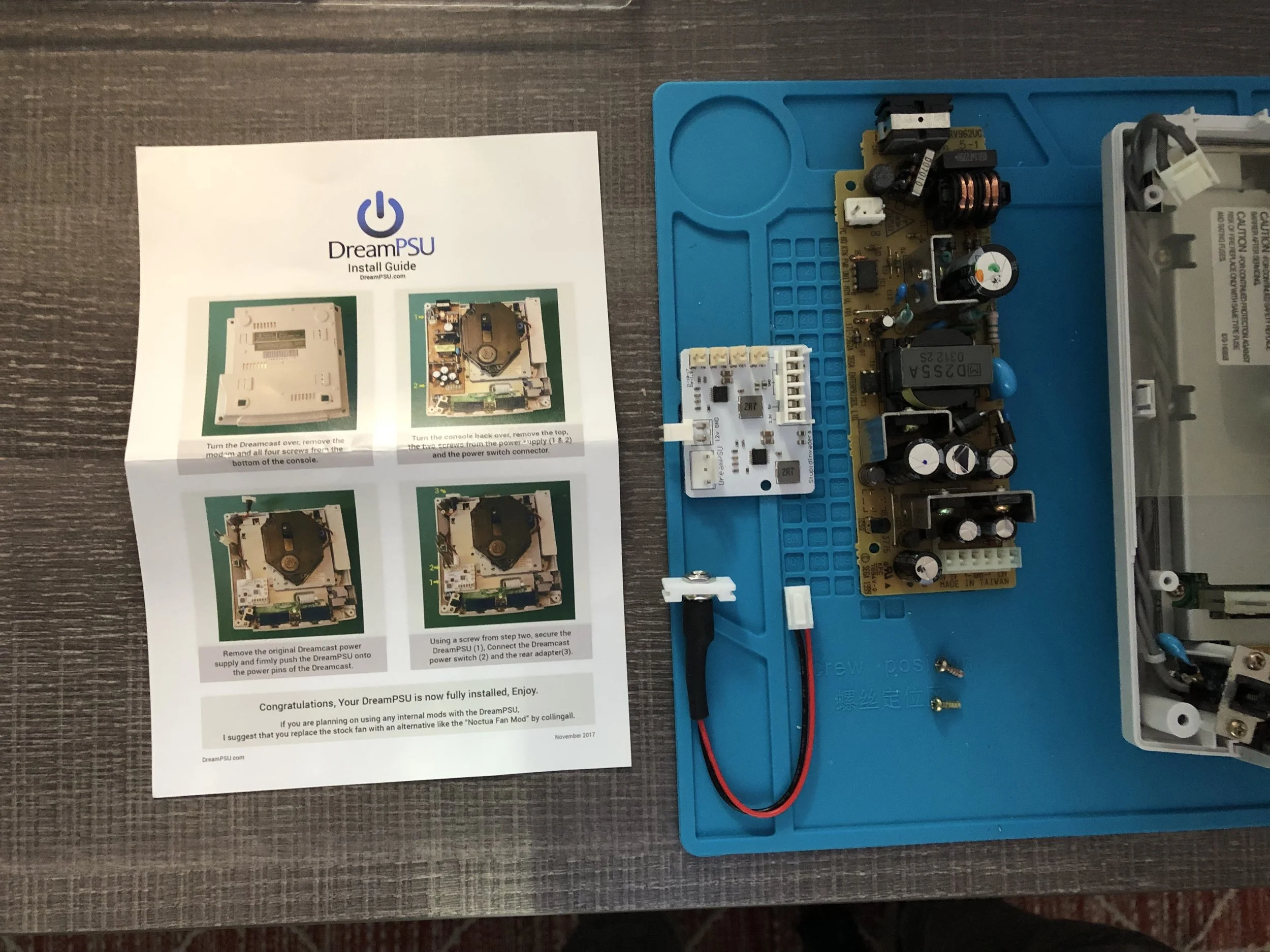
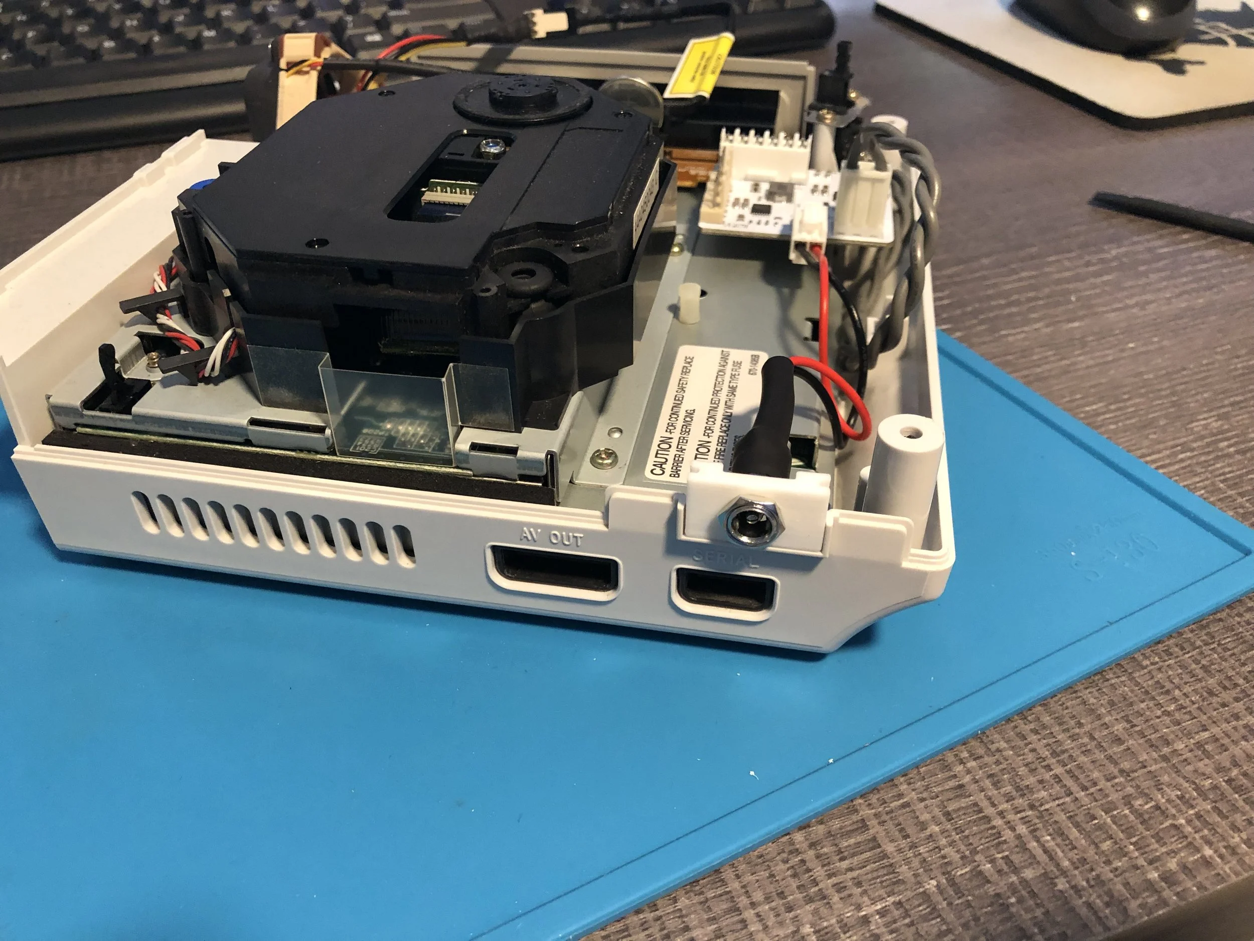
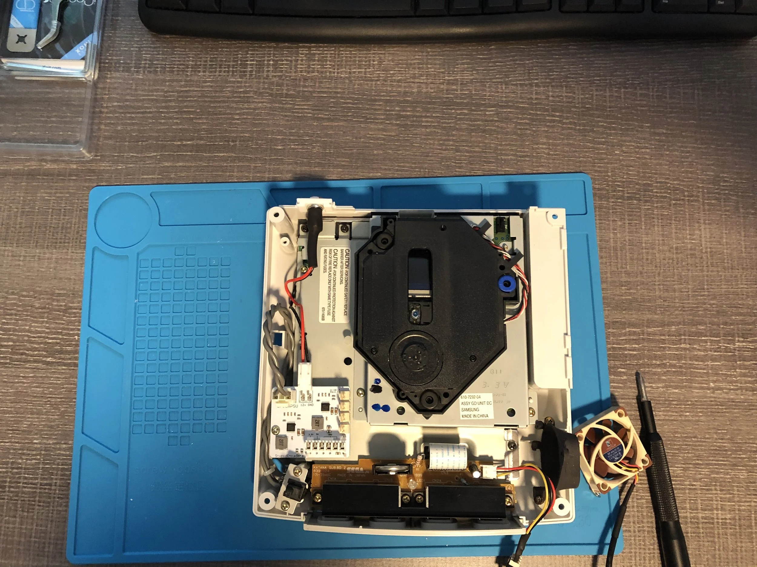
The new power supply should slot in on top of those pin connectors (which were on the lower right side of the old power supply unit). The cable we reconnected from the old unit plugs into the new one, similarly at its top left corner. And then new barrel jack-style power port plugs into the new power supply on one side the wire, and slots into the back of the console on the other.
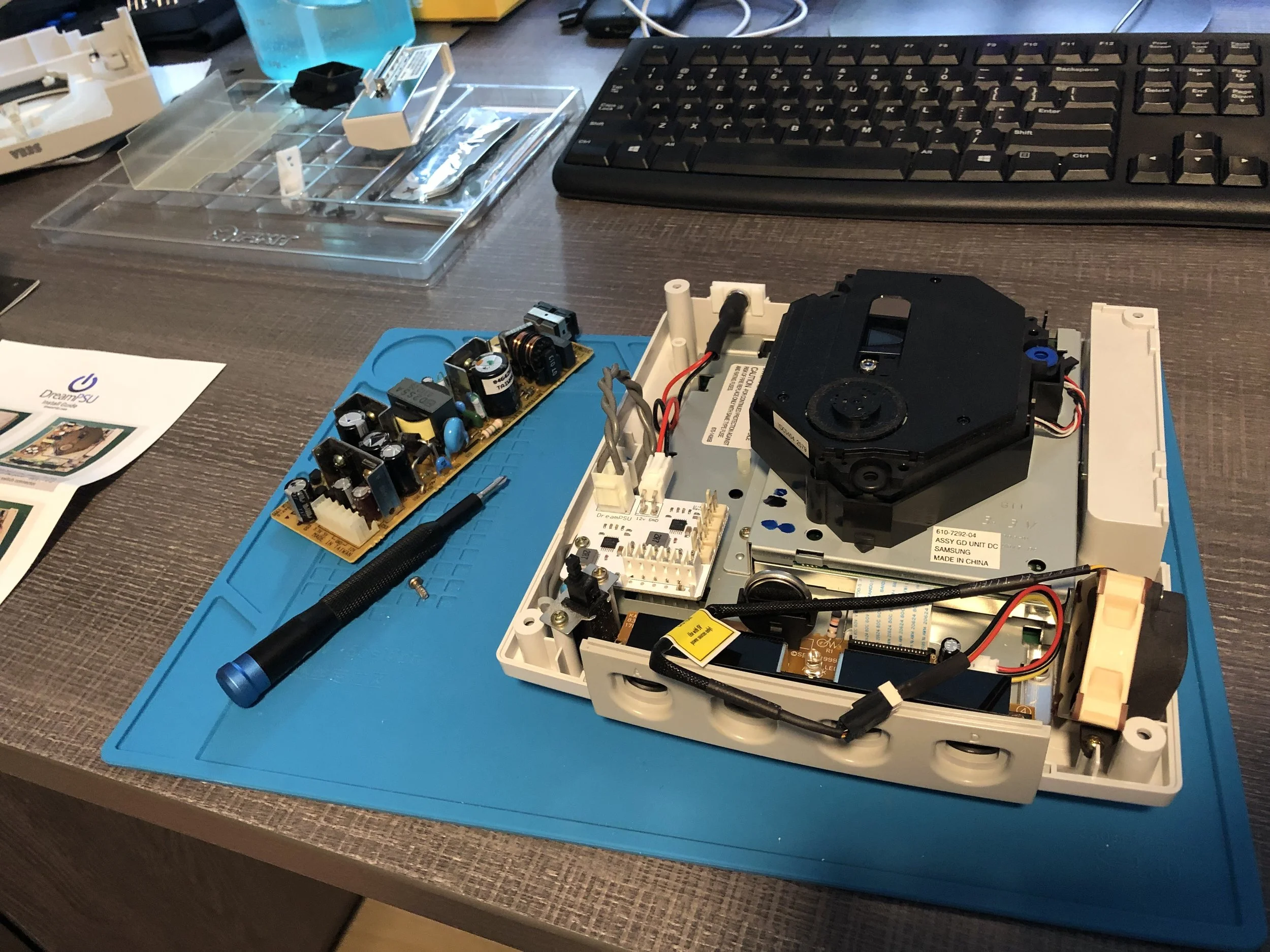
About that new barrel jack power port though: mine just barely fit into the back the Dreamcast. This piece is an extremely tight fit, to the point that I thought I was going to break something forcing it in there. I’m not sure if someone measured incorrectly or there was a 3D printing defect or whatever, but expect a difficult time forcing this new power port into place.
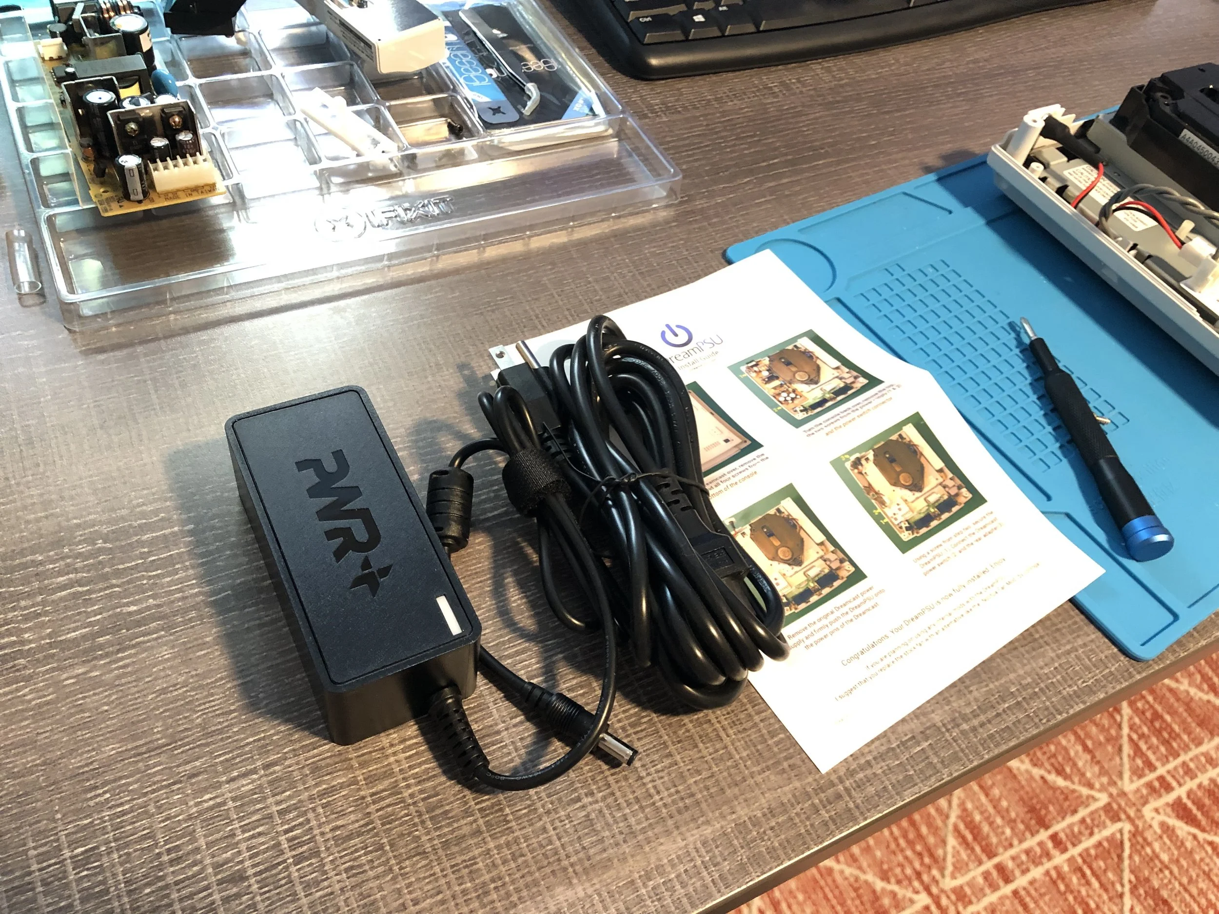
Once that is all done, you will need a new power cord (and brick) for your Dreamcast: a 12V, 5amp, barrel jack power adapter. I went with this one, but anything similar should be fine.
When it’s done, your new Dreamcast power supply unit should look like this. Geez, so much extra space!
GDEMU Installation
Another easy upgrade! Can salvage a Dreamcast if its Optical Drive is broken.
Allows you to play games from an SD card instead of game discs!
Does require downloading the GDmenu files and setting up your SD card in a specific format.
Products Used:
GDEMU Optical Drive Simulation Board Card Repair Part Optical Drive for SEGA Dreamcast Console
Software: GDmenu v0.6 for GDEMU found at GDEMU.wordpress.com/Links
The single biggest upgrade on our list, you would think that the GDEMU installation would be the most difficult, or at least the most complicated. As it turns out however, it was super easy! There is some setup required for the SD card, and that’s where more people are likely to encounter problems. But honestly, I was shocked at how straight-forward the process was. Prepare your SD card ahead of time and you can simply swap this circuit board in for your optical drive. Incredible!
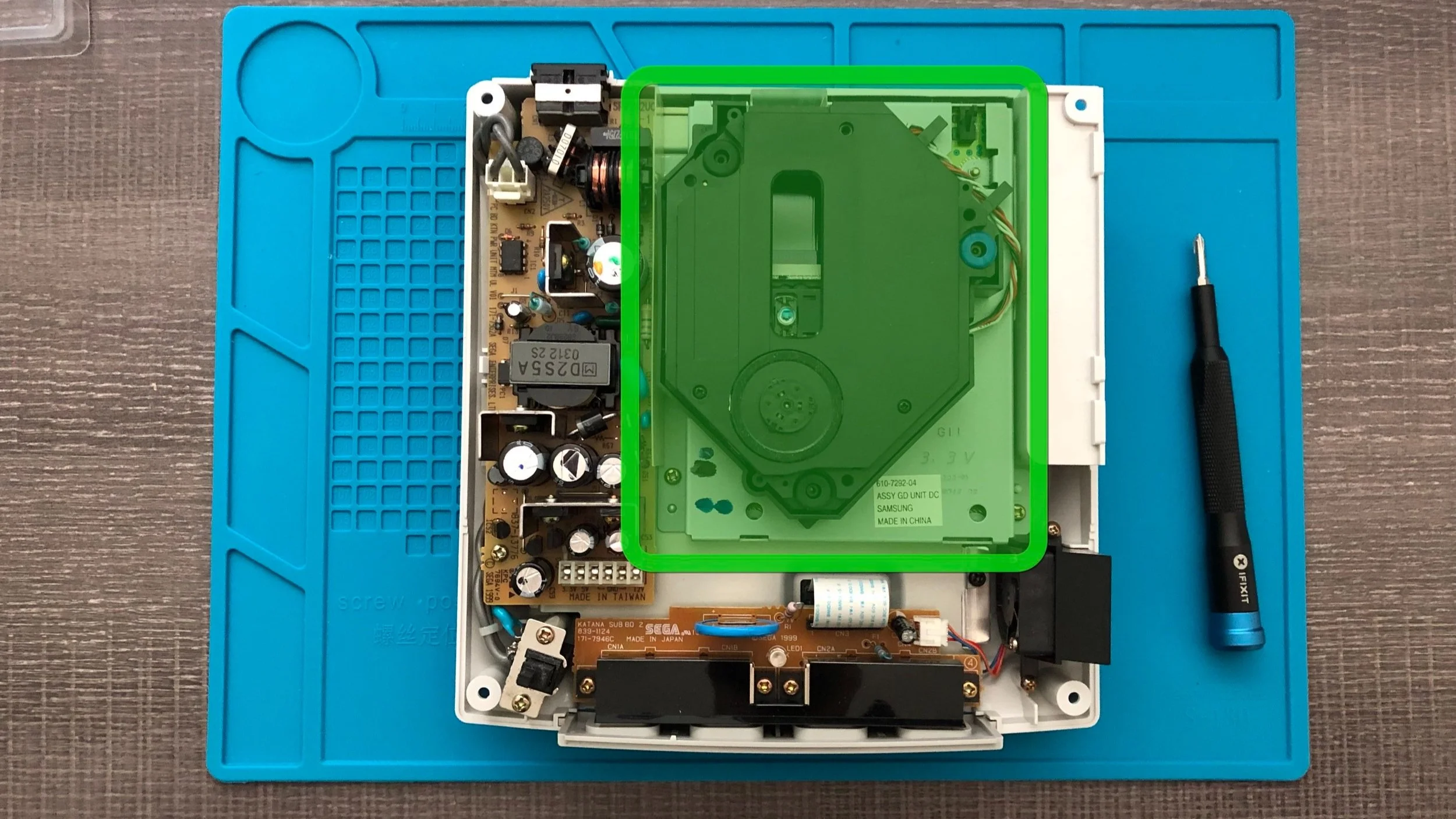
There are only three screws holding the optical drive in place. Simple remove these screws and whole optical drive should lift up and out. If the optical drive is functional, I would recommend putting somewhere for safekeeping, as you might want to reinstall it later. Or perhaps use it to replace a broken drive on another Dreamcast down the line.
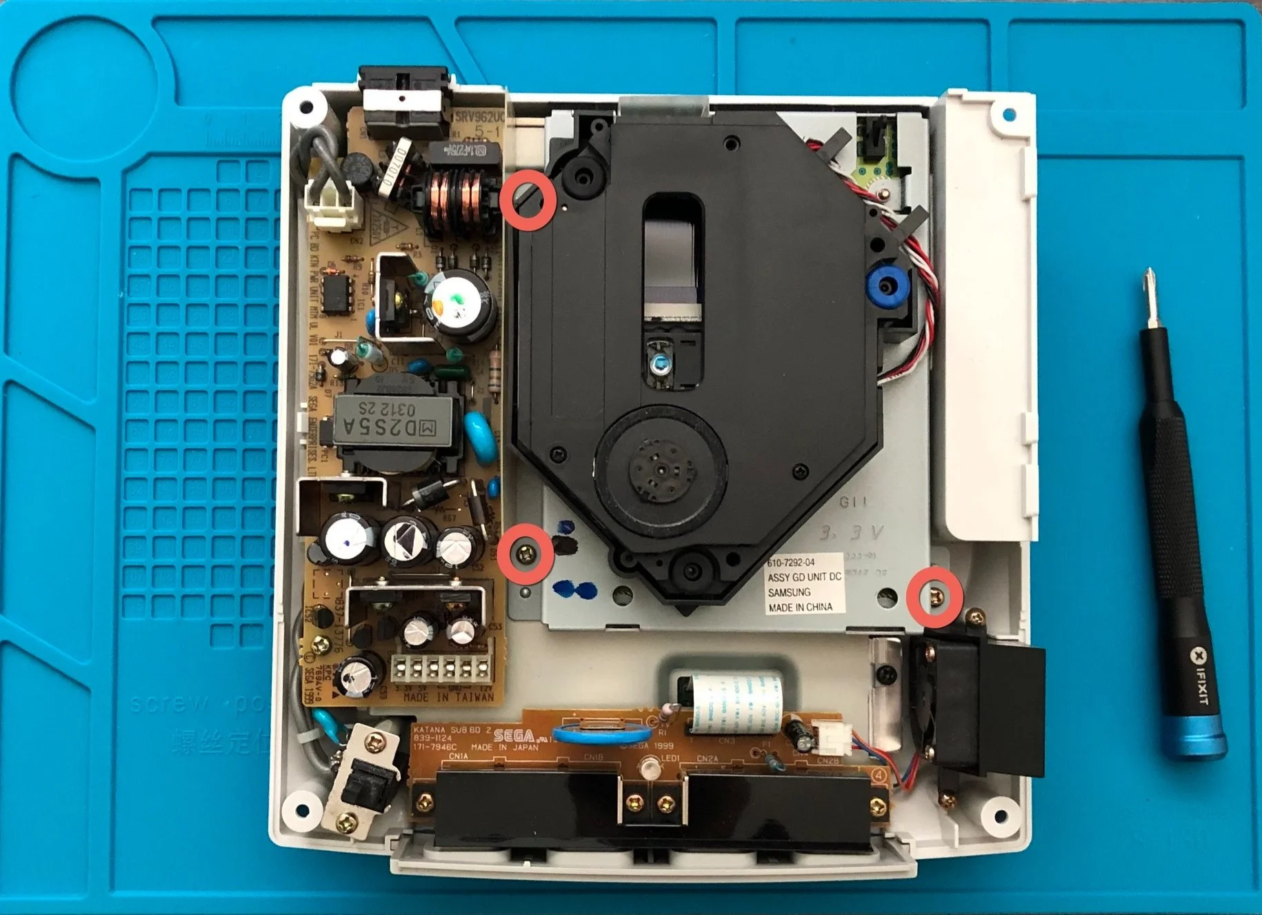
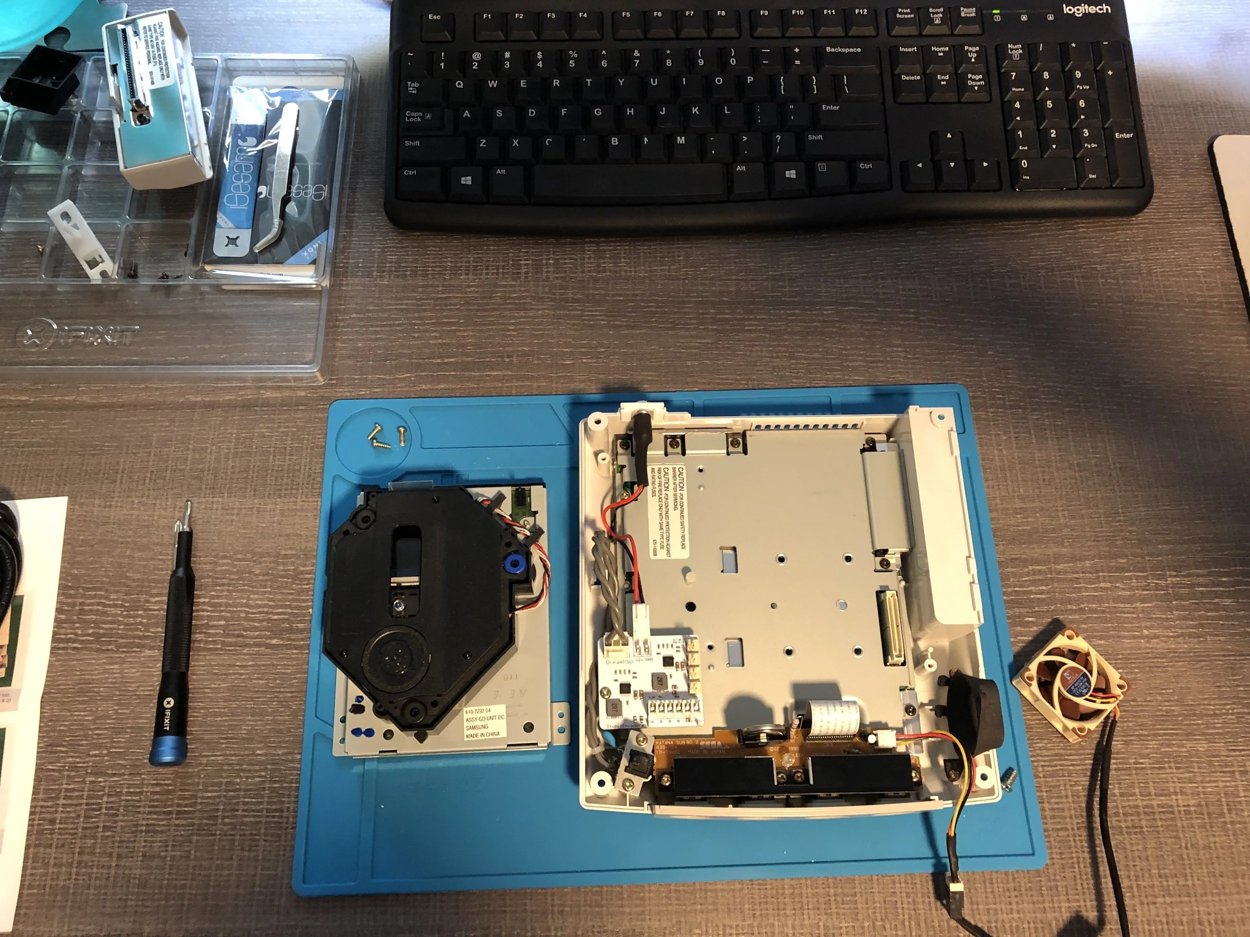
Underneath where the optical drive used to reside, on the right hand side, you will see connector port. That’s where the new GDEMU will connect to the Dreamcast.
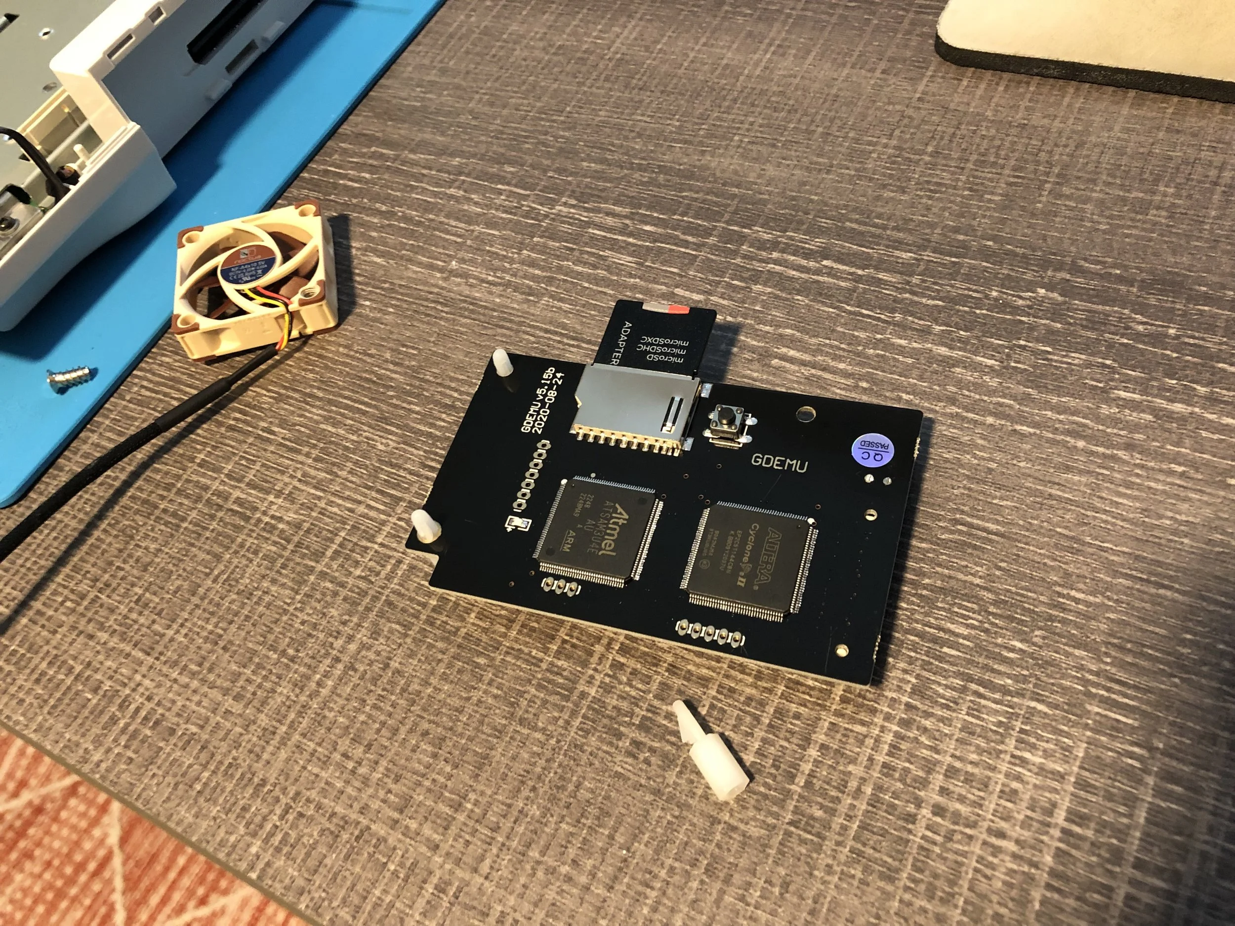
Since the GDEMU is just a little circuit board, it’s obviously much smaller than the drive you just removed. Hopefully the GDEMU you purchased included little plastic feet to help it sit securely in place. Putting those feet on the board is the next step before you place it in the console.
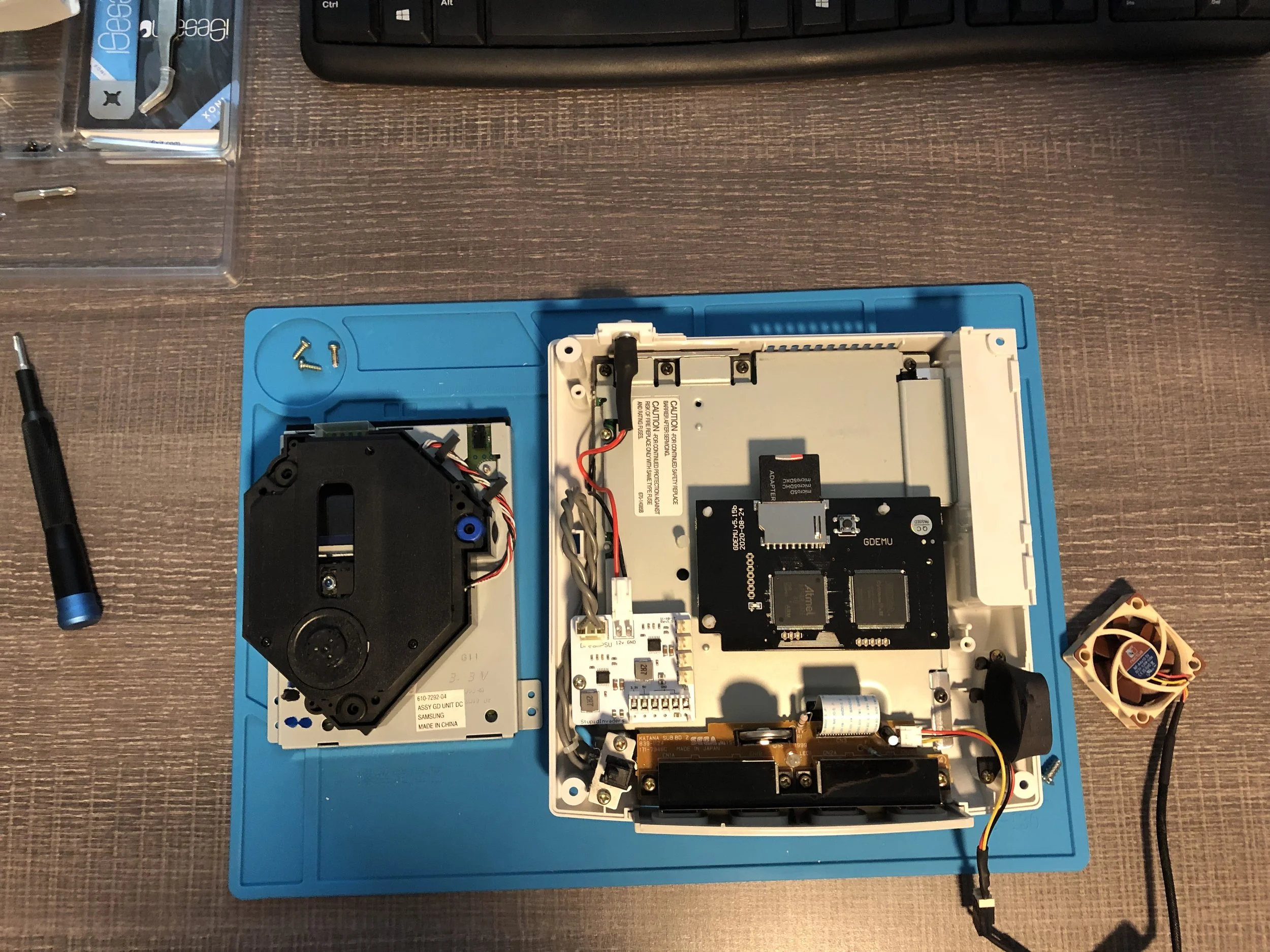
Your GDEMU should slot right into the optical drive’s connector port and, with its plastic feet in place, the circuit board should be seated comfortably in the console. And that’s it on the hardware side, all of our modifications are done!
The final step is to set up your SD card, so let’s look at that. First you will want to download the GDmenu zip archive from GDEMU.wordpress.com.
And you will also want to make sure your SD card is formatted as FAT32. Now if you’re formatting a card bigger than 64gb, Windows won’t actually let you format it as FAT32, which is what you need for the GDEMU. So you may need to use a third-party program to format the card for you.
I used Guiformatter and that did the trick. Just remember: Be EXTREMELY careful when formatting drives like this. If you accidentally select the wrong drive on a drive formatting app, you could format your computer’s hard drive, easing everything on accident. I’ve never heard of someone actually doing this, but it’s a potentially easy mistake to make.
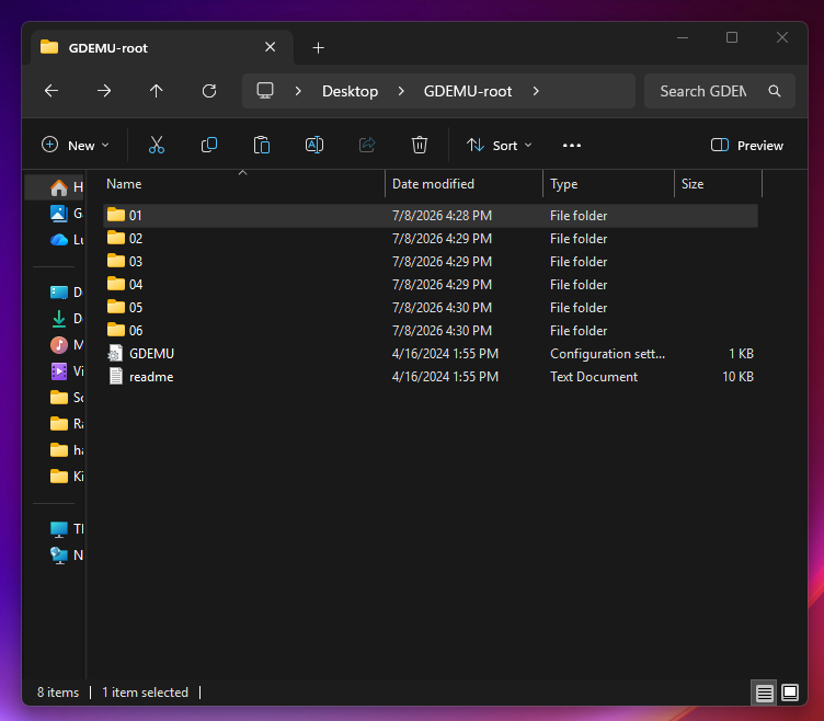
The file structure for your SD card should end up looking something like this.
Once your SD card has been formatted, we can extract the GDmenu zip archive. Copy the file GDEMU.ini and folder 01 to the root of your SD card. You can then add games as game files contained in their own folder, starting with folder 02, then 03, 04, and so on. So that’s GDEMU files in folder 01, and individual game files in subsequent folders from folder 02 onward. This is the file structure the GDEMU needs to function.
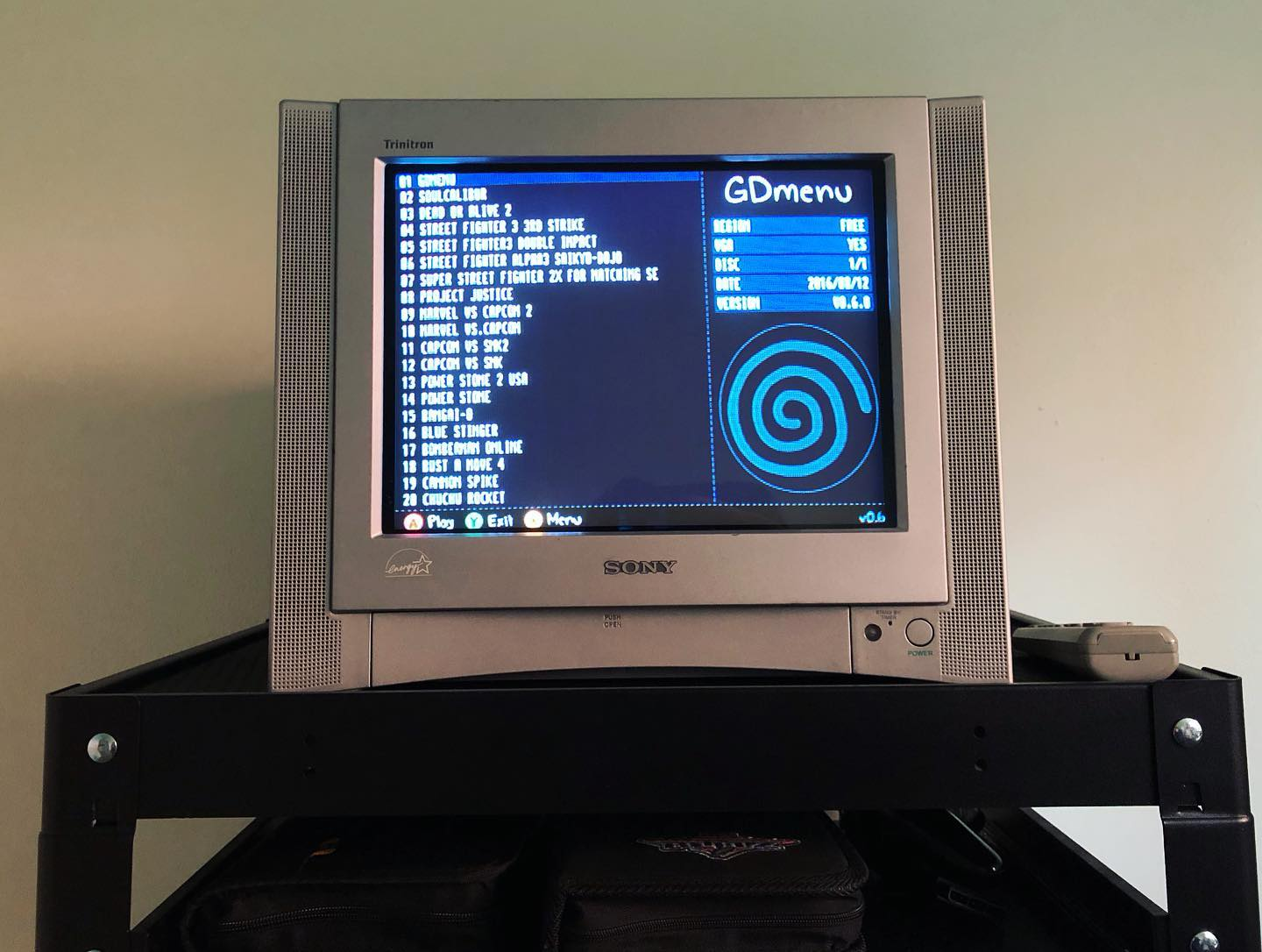
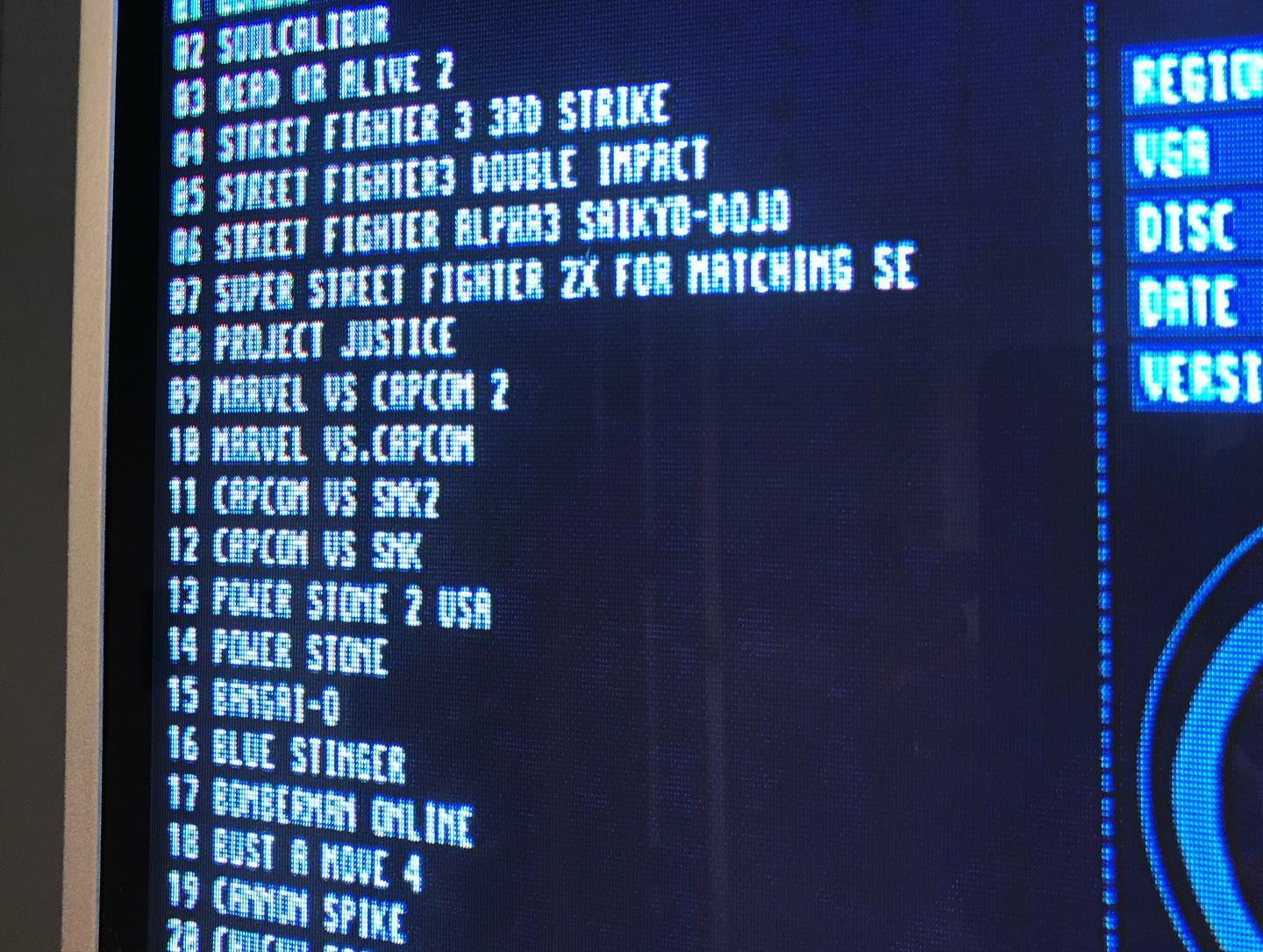
Eject the SD card from your reader, insert into your GDEMU SD slot and power-on the Dreamcast. After booting the software, a loading screen will appear while the games list is being generated. If everything went according to plan the menu will be displayed, listing all the games on the SD card.
Regarding the game files themselves, your GDEMU should be able to use either CDI or GDI. What’s the difference between these formats? Well I found a webpage that explains it pretty clearly. Basically GDI is the original Dreamcast game disc format, while CDI has been slightly compressed to fit onto a standard CD. All things being equal, GDI is the preferable to use. But CDI should also work just fine.
And that is that! Your Dreamcast should now be able to launch games from an SD card and you’ll probably never need to open the console’s disc tray ever again. Convenient!
Alright, four Dreamcast mods attempted, four Dreamcast mods completed. Hopefully you’ve found this to be somewhat useful in your own console modification adventures. If you need more guidance, there are a ton of video tutorials online that walk you through each of this projects as well. And feel free to leave a comment if you have any questions. Happy Gaming!